


G9729 Combination Lathe/Mill
-43-
I
II
III
A
120T 127T
A
24T
36 42 48 60 72
mm
mm
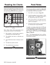
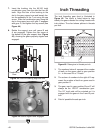
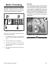
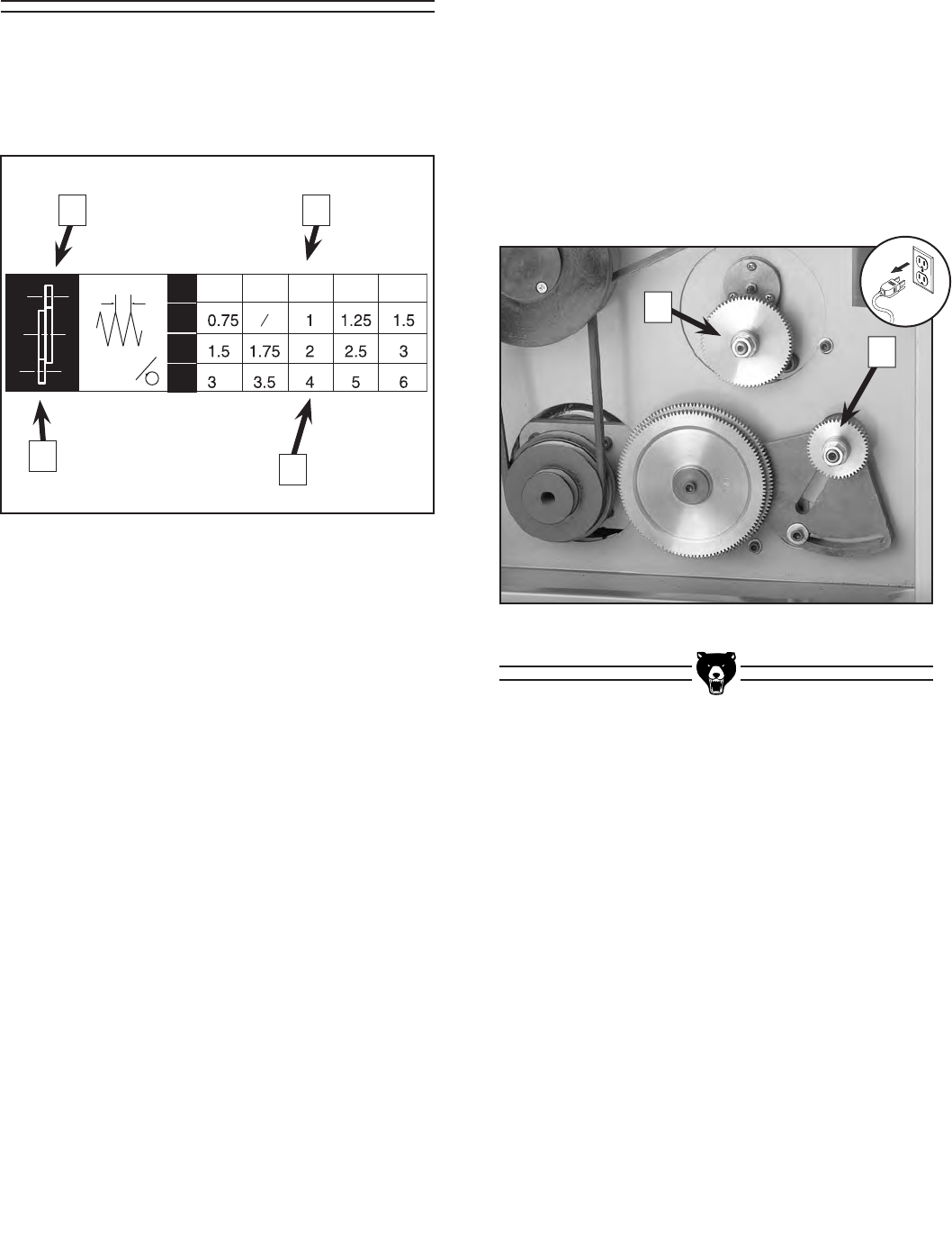
The metric threading gear chart is illustrated in
Figure 52. The
layout is listed below to help iden-
tify gears for cutting threads with metric pitches.
The chart below lists threads in millimeters.
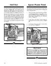
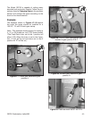
Example:
To cut a thread with a pitch of 1.25 mm we would
select a 60 tooth gear and place it in gear position
A; we would select a 24 tooth gear and place it
in gear position D (4 in Figure 52); and we would
use
the 120/127 combination gear. Please note
that the 60 tooth gear is engaged with the 127
tooth gear and the 120 gear is engaged with the
24 tooth gear. You can accomplish this by turning
the 24 tooth gear so the hub is on the inside as
in Figure
57.
Figure 52.
Metric thread pitches & gear chart.
Note—This chart reflects approximate apron
movement per revolution.
1. The
numbers to the right of A represent the
number of teeth on gears used in gear posi-
tion
A.
2. Field
of possible metric thread pitches.
3. This
gear will always be a 120/127 combi-
nation gear and will be the intermediate to
gears A and D.
4. This
gear will always have 24 teeth for metric
threading.
Metric Threading
Figure 53.
Gear D is turned so hub is on inside.
3 1
2
4
A
D