


-40-
G9729 Combination Lathe/Mill
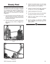
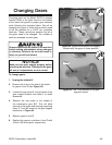
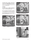
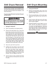
Figure 45. Gears aligned and engaged.
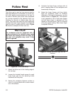
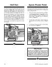
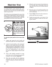
Figure 44.
Flats
on bushing align with slot.
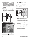
7. Insert the bushing into the 60/100 tooth
combination gear from the side that has 60
teeth. Align the flats of the bushing to the
slot in the gear support arm and loosely fas-
ten
the assembly to the T-nut using the cap
screw. Slide the combination gear along the
slot in the support arm until gear C engages
with gear D, and tighten the cap screw (see
Figure 44).
8. Rotate
the support arm until gears B and
A are engaged. Tighten the cap screw at
the bottom of the gear support arm (Figure
45), showing
the gears properly aligned and
engaged.
Bushing
Combination
Gear
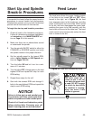
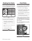
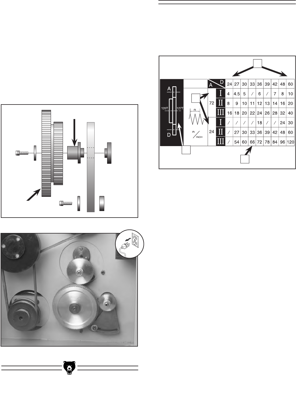
Inch Threading
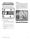
The inch threading gear chart is illustrated in
Figure 46. The
layout is listed below to help
identify the gears needed for cutting threads with
inch pitches. The chart shows pitches in threads
per inch.
Figure 46.
Rates given in threads per inch.
1. The numbers below A represent the number
of teeth on the gears used in gear position
A— in this case 24 or 72 teeth.
2. The
column of numbers to the right of D rep-
resent
the number of teeth on gears used in
gear position D.
3. The
gear used in gear position B and C will
always be the 120/127 combination gear.
The 127 tooth side will be oriented so it is
engaged with the gears in the A and D posi-
tion.
4. Field
of possible threads per inch.
4
1
3
2