


OM-494 Page 10
SECTION 3 – SPECIFICATIONS
3-1. Description
This unit has two CC/CV modules with separate weld controls for applications where two welding arcs are needed. A
Welder Selector switch controls whether one or both sets of weld output terminals are active (see Section 5-2). When
the unit is operated in the dual operator mode, each welder has CC and CV weld output available for Stick, TIG, and
MIG welding. When in the single operator mode, CC weld output is available to the welder on the Welder B (right) side
only (CV not active in single operator mode).
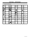
3-2. Weld, Power, And Engine Specifications
Weld
Mode
Weld
Stations
Available
Weld
Output
Weld
Output
Range
Max.
Open-
Circuit
Voltage
Rated
Welding
Output
Auxiliary Power
Rating
Engine
Fuel
Capacity
Single
1
(Right Side)
CC/DC 30 – 600 A 85
550 A at 30
Volts DC, 40%
Duty Cycle
Single-Phase,
4 kVA/kW, 34/17 A,
120/240 V AC,
Deutz F3L-912
Air-Cooled,
Dual
2
CC/DC 15 – 300 A 85
275 A at 31
Volts DC, 40%
120/240 V AC,
50/60 Hz
(4 kVA/kW Shared By
Air-Cooled,
Three-Cylinder,
41.5 HP Diesel
Engine
22.3 gal
(84.4 L)
Dual
(Both Sides)
CV/DC 10 – 32 V 49
Volts DC, 40%
Duty Cycle
All Receptacles)
Engine
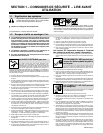
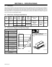
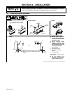
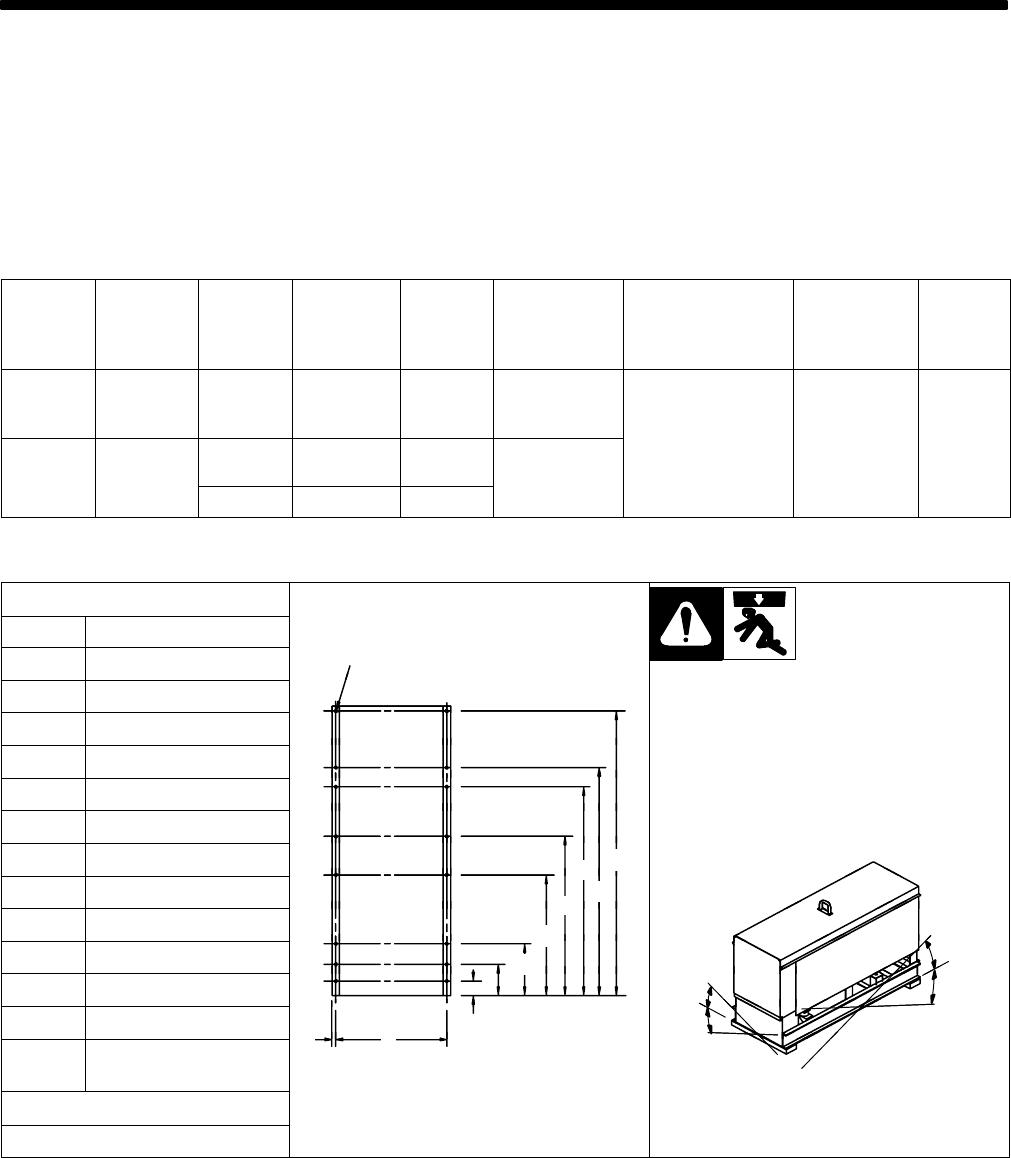
3-3. Dimensions, Weights, And Operating Angles
Dimensions
Height 47-5/8 in (1210 mm)
Width 31-1/4 in (794 mm)
L
Y
Depth 60-1/2 in (1537 mm)
Engine End
Y Do not exceed tilt angles or engine could
be damaged or unit could tip.
A 59-1/8 in (1502 mm)
be damaged or unit could tip.
Y Do not move or operate unit where it could
B 47-1/4 in (1200 mm)
Y
tip.
C 43-1/4 in (1099 mm)
D 32-3/4 in (832 mm)
E 24-15/16 in (633 mm)
A
F 10-1/2 in (267 mm)
B
C
G 6-1/2 in (165 mm)
D
°
H 2-7/8 in (73 mm)
E
F
17.5°
J 29-7/8 in (759 mm)
F
20°
17.5°
K 11/16 in (24 mm)
G
H
20°
20
L
21/32 in (17 mm) Dia.
16 Holes
H
J
K
angles_1 8/99
Weight
158 699
angles_1 8/99
2005 lb (909 kg)