


OM-494 Page 14
SECTION 4 – NSTALLATION
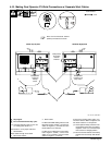
When facing the front panel, the Welder B controls and weld terminals are on the
right and the Welder A controls and weld terminals are on the left.
NOTE
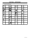
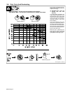
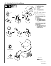
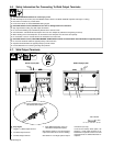
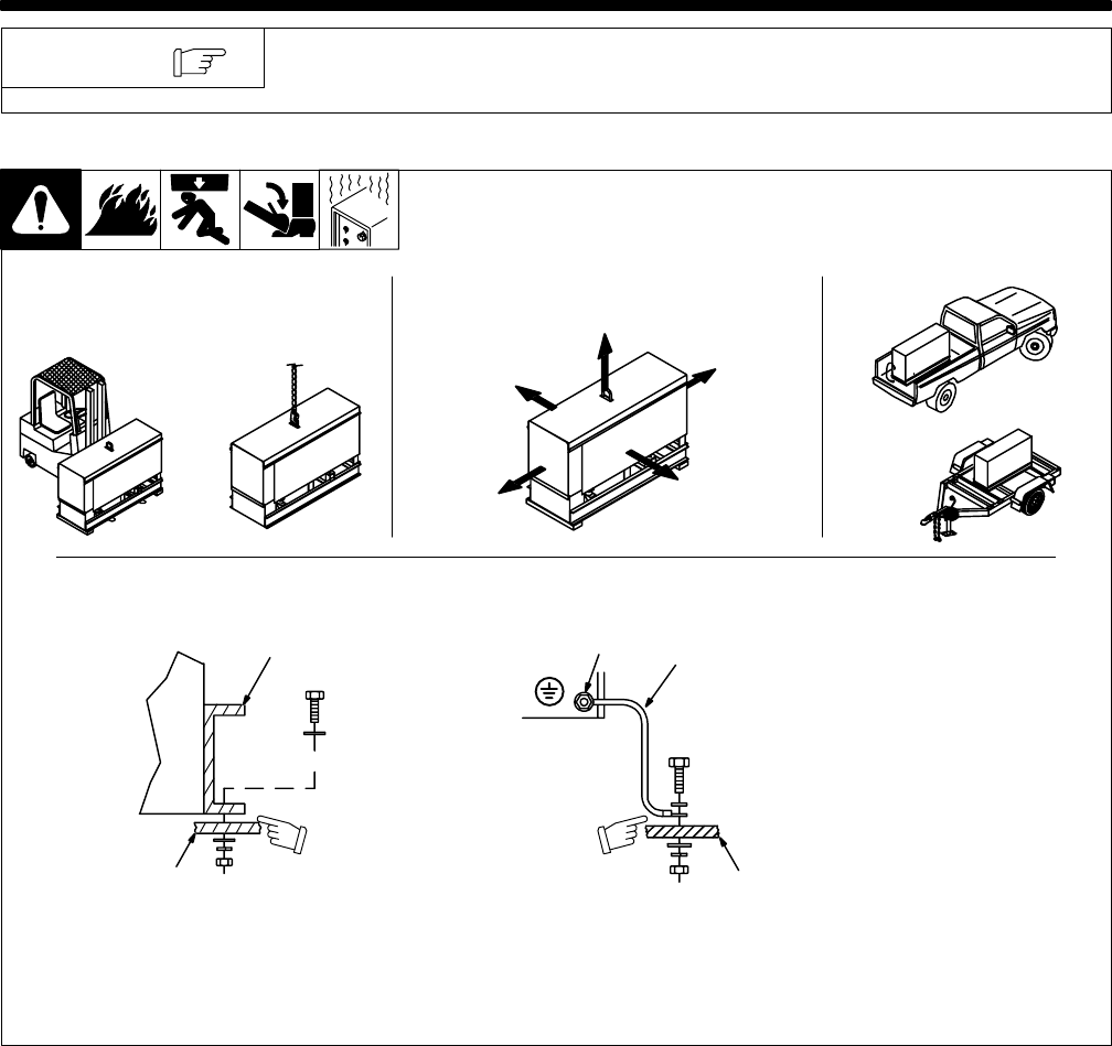
4-1. Installing Welding Generator
install1 10/00* – Ref. 800 652 / Ref. 800 477-A / 158 936-A / S-0854
1
2
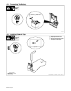
Electrically bond generator frame to
vehicle frame by metal-to-metal
contact.
GND/PE
3
4
Y Always ground generator
frame to vehicle frame to pre-
vent electric shock and static
electricity hazards.
Y Always securely fasten
welding generator onto
transport vehicle or trailer
and comply with all DOT and
other applicable codes.
1 Generator Base
2 Metal Vehicle Frame
3 Equipment Grounding
Terminal
4 Grounding Cable
Use #10 AWG or larger insulated
copper wire.
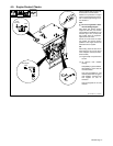
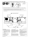
Y Be sure equipment con-
nected to the 240 V recep-
tacles is GFCI-protected.
2
OR
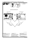
18 in
(460 mm)
18 in
(460 mm)
18 in
(460 mm)
18 in
(460 mm)
18 in
(460 mm)
OR
Movement Airflow Clearance Location
Grounding
OR
Y Do Not Lift Unit From End