


OM-494 Page 25
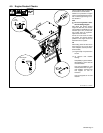
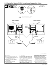
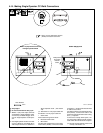
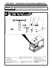
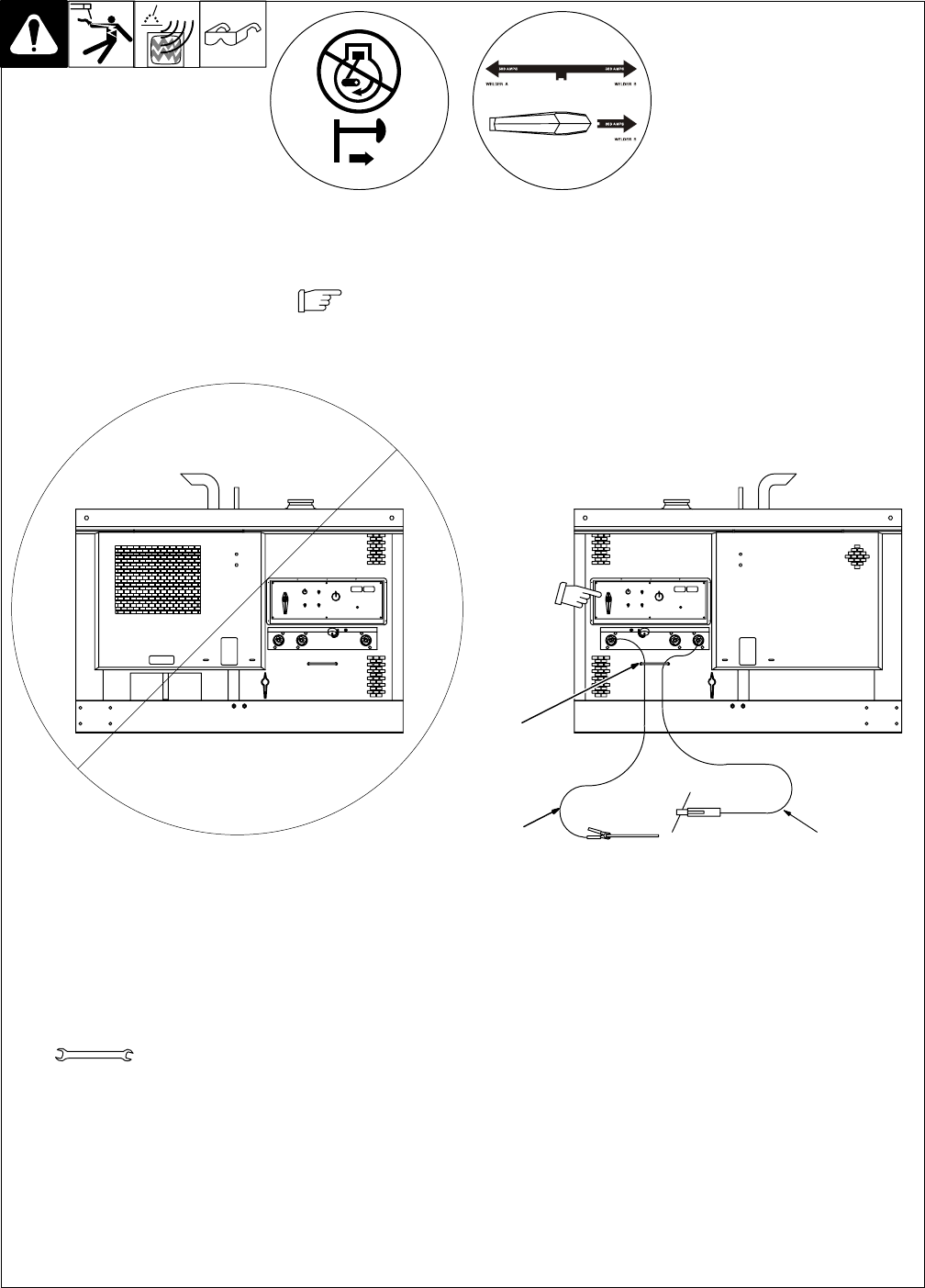
4-14. Making Single Operator CC Weld Connections
190 377 / 802 292-A
Y Stop engine.
Y Do not exceed machine duty cycle.
. Welder A (left) weld output terminals
are disabled in Single Operator mode.
Connect only to Welder B (right) termi-
nals for Single Operator mode opera-
tion.
. Use Single Operator mode for CC weld-
ing only. Welder A and Welder B CV
weld output terminals are disabled in
Single Operator mode. (see Section
4-8).
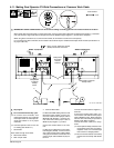
. See Section 4-15 for proper cable size.
See Section 4-15 for proper cable size.
1 Strain Relief
Route cables through strain reliefs.
2 Electrode Holder Cable
3 Work Cable
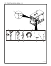
For Stick/TIG welding Direct Current Elec-
trode Positive (DCEP), connect work cable
to Negative (–) terminal and electrode hold-
er cable to CC terminal.
For Stick/TIG Direct Current Electrode Neg-
ative (DCEN), connect work cable to CC
terminal and electrode holder cable to Neg-
ative (–) receptacle.
If unit has the Polarity switch option, con-
nect work cable to Work terminal and elec-
trode holder cable to Electrode receptacle.
. Be sure Process Selector switch is set
correctly. See Section 5-3.
Tools Needed:
3/4 in
Welder B(Right) Side
Welder A (left) Terminals Inactive
In Single Operator Mode
1
3
2
Direct Current Electrode Positive
(DCEP) connections are shown.
Note position
of Process
Selector
switch.