


OM-494 Page 43
Trouble Remedy
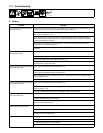
High weld output on both sides. Have Factory Authorized Service Agent check field current regulator board PC4.
Erratic weld output on either side. Check and tighten connections inside and outside unit.
Be sure connection to work piece is clean and tight.
Use dry, properly stored electrodes.
Remove excessive coils from weld cables.
Check Process Selector switch(s) connections and contacts.
Have Factory Authorized Service Agent check Welder Selector switch S2.
Low open-circuit voltage on both sides. Check engine speed, and adjust if necessary (see Section 7-5).
Have Factory Authorized Service Agent check field current regulator board PC4.
Low open-circuit voltage on either side. Increase Amperage/Voltage control setting.
Have Factory Authorized Service Agent check main rectifiers SR2 and SR3, synchronization trans-
formers T5 thru T10, and control board PC1 or PC5.
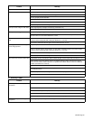
No control of weld output on either
side.
Place A/V Control switch in Panel position, or place switch in Remote position and connect remote
control to remote receptacle RC8 or RC9 (see Sections 4-17 and 5-3).
Have Factory Authorized Service Agent check control board PC1 or PC5.
No voltage control on either side; open-
circuit voltage present.
Repair or replace remote device.
Place A/V Control switch in Panel position, or place switch in Remote position and connect remote
control to remote receptacle RC8 or RC9 (see Sections 4-17 and 5-3).
Check connections to Remote receptacle RC8 and RC9.
Have Factory Authorized Service Agent check control board PC1 or PC5.
Wire feeder does not work (either side). Reset Welder A (left) circuit breaker CB5 or Welder B (right) circuit breaker CB6 (see Section 7-10).
Check position of Process Selector switches and Welder Selector switch. All weld output stops if
either Process Selector switch is placed in CV position when Welder Selector switch is in Welder B
position (see Sections 5-1 and 5-3).
Check connections to Remote 14 receptacle RC8 (see Section 4-17).
Place optional Polarity switches in Reverse position. There is no CV weld output when Polarity switch
is in Straight position.
Have Factory Authorized Service Agent check brushes and slip rings, and field excitation circuit.
Repair or replace wire feeder.
B. Auxiliary Power
Trouble Remedy
No output at auxiliary power
receptacles.
Reset receptacle circuit breakers (see Section 6-1).
Press GFCI reset button on 120 volt GFCI receptacles (see Section 6-1).
Check fuse F1, and replace if open (see Section 7-10).
Check receptacle(s) for continuity and proper connections. Replace receptacle(s) if necessary.
Have Factory Authorized Service Agent check brushes and slip rings.
High or low output at auxiliary power
receptacles.
Check engine speed, and adjust if necessary (see Section 7-5).