


OM-494 Page 31
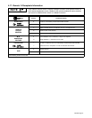
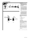
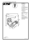
5-3. Weld Control Descriptions (See Section 5-2)
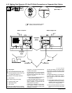
1 Welder Selector Switch
Use switch to select Dual Operator or Single
Operator welding mode.
Place switch in Welder A/Welder B (dual oper-
ator) position for CC and CV output from Weld-
er A (left) and Welder B (right) weld output ter-
minals. Control the weld output from the termi-
nals on each side using the weld controls on
that same side.
Place switch in Welder B (single operator)
position for CC weld output from Welder B
(right) weld output terminals only. CV weld out-
put terminals on both sides do not work when
unit is in Single Operator mode.
. Welder A (left) weld output terminals are
disabled in Single Operator mode. Con-
nect only to Welder B (right) terminals for
Single Operator operation.
. When in single Operator mode, only CC
weld output is available. Welder A (left)
and Welder B (right) side CV weld output
terminals are disabled in Single Operator
mode. (see Section 4-8).
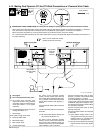
2 Process Selector Switch
Use switch to select output for weld process.
If switch is in Stick/Tig position, place Welder
Selector switch in Welder A/Welder B or Weld-
er B Position. If switch is in MIG position, place
Welder Selector switch in Welder A/Welder B
position only.
. CV weld output for MIG is only available
when Welder Selector switch is in Welder
A/Welder B position. All weld output
stops if either Process Selector switch
is placed in MIG position when Welder
Selector switch is in Welder B position.
. Place optional Polarity switch in Reverse
position when using CV weld output.
There is no CV weld output when Polarity
switch is in Straight position.
Y Do not switch under load or with out-
put on.
3 Arc Force (Dig) Control
Use control to automatically increase amper-
age as arc length is decreased to assist in arc
starts and reduce the chance of the electrode
sticking in the puddle. Turn clockwise to in-
crease short-circuit amperage. Set at mini-
mum for TIG welding.
4 Hot Start Switch
Use switch to disable hot start circuit. Turn
switch On for Stick (SMAW) and Submerged
Arc (SAW) Welding, and Air Carbon Arc Cut-
ting and Gouging (CAC-A). Turn switch Off for
TIG (GTAW) welding.
When switch is in On position, higher short-cir-
cuit amperage helps arc starting. After arc
starts, the front panel or remote Amperage/
Voltage control setting determines weld am-
perage.
. The hot start circuit does not function
when constant voltage (CV) welding.
5 Amperage/Voltage Control
When Process Selector switch is in the Stick/
TIG position, turn control clockwise to in-
crease amperage. Read amperage from outer
scale of control. The Amperage/Voltage con-
trol adjusts amperage only when constant cur-
rent (CC) welding and does not adjust open-
circuit voltage.
When Process Selector switch is in the MIG
position, turn control clockwise to increase
voltage. Voltmeter value changes as control
knob is turned. Control can be adjusted while
welding.
. When Welder Selector switch is in Welder
B position (single operator mode), weld
amperage is two times the value selected
by the Amperage/Voltage control. For ex-
ample, if Amperage/Voltage control is set
to 250 A, weld output is actually 500A.
6 Weld Meters
With Process Selector switch in the Stick/Tig
position, meters read 0 (zero) with contactor
off. Meters display actual output voltage and
amperage with contactor on.
With Process Selector switch in the MIG posi-
tion, voltmeter displays preset voltage with
contactor off. Voltmeter and ammeter display
actual output voltage and amperage with con-
tactor on.
7 High Temperature Shutdown Light
Light goes on and weld output stops if weld
rectifier gets too warm. Let unit cool before
welding.
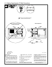
8 Remote Amperage/Voltage Control
Switch
For front panel control, place switch in Panel
position. For remote control, place switch in
Remote position, and connect remote device
(see Section 4-17).
9 Output (Contactor) Switch
For front panel control of output, place switch
in On (Hot) position. For remote control of out-
put, place switch in Remote position, and con-
nect remote device (see Section 4-17).
Y Weld output terminals are energized
when Output (Contactor) switch is On
and engine is running.
10 Polarity Switch (Optional)
Y Do not switch under load.
Use switch to change polarity of weld output
(see Sections 4-7 thru 4-14).
. Place optional Polarity switch in Reverse
position when using CV weld receptacle.
There is no CV weld output when switch is
in Straight position.