


OM-494 Page 21
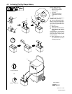
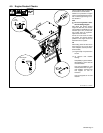
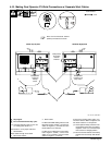
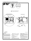
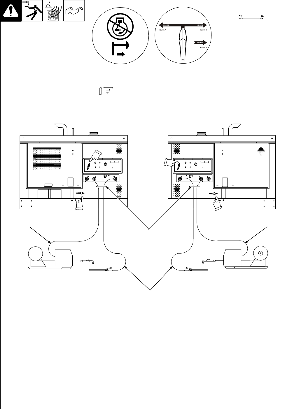
4-10. Making Dual Operator CV Weld Connections w/ Separate Work Cables
Ref. 190 377 / 802 292-A
Y Stop engine.
Y Do not exceed machine duty cycle.
. Use Dual Operator mode for CC and
CV welding (see Section 5-1).
See Section 4-15 for proper cable size.
1 Strain Reliefs
Route cables through strain reliefs.
2 Wire Feeder Cables
3 Work Cables
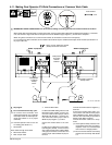
For MIG and FCAW welding Direct Current
Electrode Positive (DCEP), connect work
cables to Negative (–) terminals and wire
feeder cables to CV terminals.
For MIG and FCAW Direct Current Elec-
trode Negative (DCEN), connect work
cables to CV terminals and wire feeder
cables to Negative (–) terminals.
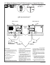
If unit has the Polarity switch option, con-
nect work cables to Work receptacles and
wire feeder cables to CV receptacles.
. Place optional Polarity switches in Re-
verse position when using CV weld re-
ceptacles. There is no CV weld output
when switch is in Straight position.
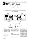
. Be sure Process Selector and Polarity
switches are set correctly. See Section
5-3.
Tools Needed:
Welder A (Left) Side
3/4 in
Welder B (Right) Side
1
2
3
2
Direct Current Electrode Positive
(DCEP) connections are shown.
Note position
of Process
Selector
switches.
Note position
of optional
Polarity
switch.
Note position
of optional Po-
larity switch.