


OM-494 Page 24
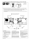
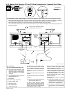
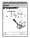
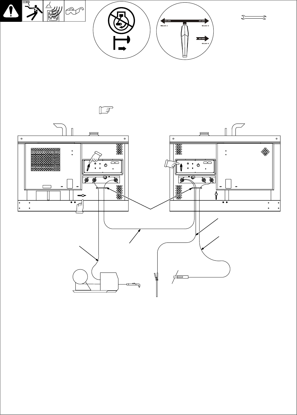
4-13. Making Dual Operator CC And CV Weld Connections w/ Common Work Cable
Ref. 190 377 / 802 292-A
Y Stop engine.
Y Do not exceed machine duty cycle.
. For common work connection, work
cable must be able to carry combined
weld output of both CC weld output ter-
minals (see Section 4-15 for proper
cable size).
. Use Dual Operator mode for CC and CV
welding (see Section 5-1).
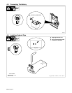
1 Strain Reliefs
Route cables through strain reliefs.
2 Electrode Holder Cable
3 Wire Feeder Cable
4 Work Jumper Cable
5 Common Work Cable
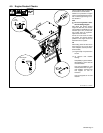
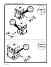
For Direct Current Electrode Positive
(DCEP), connect common work cable and
work jumper cable to Welder B (right) Nega-
tive (–) terminal. Connect other end of work
jumper cable to Welder A (left) Negative (–)
terminal.
Connect electrode holder cable to either CC
terminal.
Connect wire feeder cable to CV terminal on
other side.
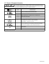
. Be sure Process Selector switches are
set correctly. See Section 5-3.
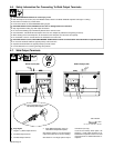
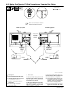
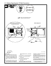
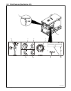
For Direct Current Electrode Negative
(DCEN), connect common work cable and
work jumper cable to Welder B (right) CC
terminal. Connect other end of work jumper
cable to Welder A (left) CV terminal.
Connect electrode holder cable to either
Negative (–) terminal, and wire feeder cable
to remaining Negative (–) terminal.
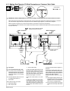
If unit has the Polarity switch option, connect
common work cable and work jumper cable
to Welder B (right) Work receptacle. Con-
nect other end of work jumper cable to Weld-
er A (left) Work receptacle.
Connect electrode holder cable to either
Electrode receptacle.
Connect wire feeder cable to CV receptacle
on other side.
. Place optional Polarity switch in Re-
verse position when using CV weld re-
ceptacle. There is no CV weld output
when switch is in Straight position.
. Be sure Process Selector and Polarity
switches are set correctly. See Section
5-3.
Tools Needed:
Welder A (Left) Side
3/4 in
Welder B (Right) Side
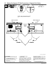
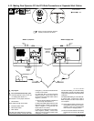
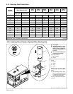
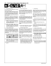
Y INADEQUATE CABLE CONNECTIONS can cause serious damage to welding generator and create a hazardous condition.
When making weld connections with a common work cable, connect a weld cable of adequate size between the Negative (–) weld termi-
nals, and connect a single weld cable of adequate size from the Welder B (right) Negative (–) terminal to the workpiece.
When using these connections as a common work terminal, all connections must be of the same polarity.
For a common work cable connection, the work cable must be able to carry the combined weld output of both modules (see Section 4-15
for proper cable size).
1
2
3
4
5
Direct Current Electrode Positive
(DCEP) connections are shown.
Note position
of Process
Selector
switches.
Note position of
optional Polarity
switch.