


OM-494 Page 50
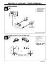
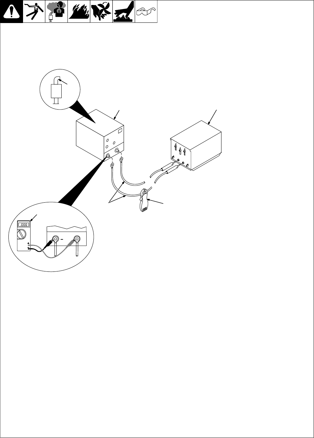
9-3. Run-In Procedure Using Resistance Grid
S-0684
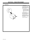
Y Stop engine.
Y Do not touch hot exhaust
pipe, engine parts, or load
bank/grid.
Y Keep exhaust and pipe away
from flammables.
1 Resistance Grid
Use grid sized for generator rated
output.
Turn Off grid.
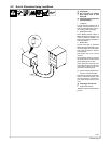
2 Welding Generator
Place Welder Selector switch in
Welder B position (600 Amps), A/V
control in minimum position, and
both Process Selector switches in
Stick/TIG position.
3 Weld Cables
Connect grid to generator Welder B
(right) weld output terminals using
proper size weld cables with cor-
rect connectors (polarity is not im-
portant).
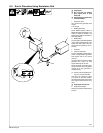
4 Voltmeter
5 Clamp-On Ammeter
Connect voltmeter and ammeter as
shown, if not provided on generator.
Start engine and run for several
minutes.
Set grid switches and then adjust
generator A/V control so load
equals 350 Amps at 40 volts.
Check generator and meters after
first five minutes then every fifteen
minutes to be sure generator is
loaded properly.
. Check oil level frequently dur-
ing run-in; add oil if needed.
After one hour (minimum), place
A/V control in minimum position,
then shut down grid to remove load.
Run engine several minutes at no
load.
Y Stop engine and let cool.
6 Engine Exhaust Pipe
Repeat procedure if wetstacking is
present.
1
3
2
5
6
+
4