


OM-494 Page 18
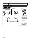
4-6. Safety Information For Connecting To Weld Output Terminals
Y UNEXPECTED WELD OUTPUT can cause injury or fire.
D Both weld outputs can be live (ON) when Welder Selector switch is in Welder A/Welder B position and engine is running.
D Disconnect or insulate any unused cables.
D Know where cables are located BEFORE starting engine.
Y ELECTRIC SHOCK can kill; ARCING can burn skin or damage electrical connections.
D Stop engine before making any weld output connections.
D Do not connect welding output of different polarities to the same structure.
D See ANSI Z49.1 and OSHA Title 29, Chapter XVII, Part 1910, Subpart Q (addresses at beginning of manual).
D When welding on the same workpiece, all connections to the workpiece must be of the same polarity.
D Do not handle or come in contact with two live electrodes at the same time.
Y ELECTRIC SHOCK can kill; TWO TIMES NORMAL OPEN-CIRCUIT VOLTS can exist between electrode holders of opposite polarity.
D Do not touch electrode holders of opposite polarity at the same time.
D Separate electrode holders of opposite polarity to prevent contact.
D Consult ANSI Z49.1 for common grounding safe practices.
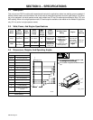
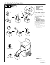
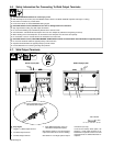
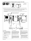
4-7. Weld Output Terminals
Ref. 190 377 / 802 292-A / 802 554
Y Stop engine.
1 Negative (–) Weld Output Terminal
2 CV Weld Output Terminal
3 CC Weld Output Terminal
4 Dinse Weld Receptacles (Only On
Units With Polarity Switch Option)
See Sections 4-8 thru 4-13 for dual operator
output connections for CC and CV welding.
See Section 4-14 for single operator output
connections (CC only).
If unit has the Polarity switch option, the
Negative (–) weld output terminals are la-
beled Work receptacles and the CC weld
output terminals are labeled Electrode re-
ceptacles.
Tools Needed:
3/4 in
Welder B (Right) Side
123
Welder A (Left) Side
123
. Dinse receptacles only on units
with Polarity switch option.
4