


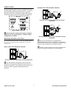


RUN INPUT
0V
RUN
READY
ALARM
+V
MAIN (LINE) CONTACTOR
C04
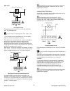
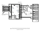
Run Signal Circuit
The RUN input will accept 12V to 250V AC (50/60Hz)
only. DC cannot be used.
Do not connect a voltage greater than 250V to this
input.
12V to 250Vac must be applied to the “run” terminals
when the compressor motor is running.
This input can be connected to the control terminals A1
and A2 (coil) of the main starter contactor of the
compressor. When the compressor control system
energizes the main contactor, the IR-PCB will detect the
voltage across the contactor coil terminals and signal the
X4I that the compressor is running.
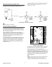
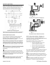
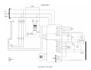
Alternatively, if the main contactor coil voltage is greater
than 250Vac, a contactor auxiliary switch can be used to
apply a suitable voltage to the “run” input terminals.
0V
+V
MAIN (LINE) CONTACTOR
0V
+V
AUXILIARY SWITCH
RUN
READY
ALARM
C04
Run Signal Circuit with Auxiliary Switch
In instances where a motor starter contactor is not
available or accessible, any part of a compressor control
circuit that is energized when the compressor is running
can be monitored. For example: fan contactor or voltage
signal to a remote starter.
The IR-PCB input common terminal must always be
connected to the neutral, common or 0V line of the
applied input voltage.
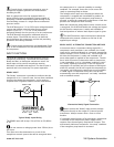
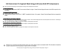
WARNING INPUT (OPTIONAL)
The IR-PCB is equipped with a warning input that can be
used to detect warning conditions.
An alarm that stops the compressor, and/or
prevents the compressor from running is determined
from the “run” and “ready” inputs. Warning detection is
optional and is not a requirement.
Alarm Run Ready
Alarm Lamp
0V
+V
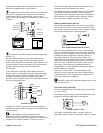
C04
Warning Input Circuit
The warning input will accept 12V to 250V AC (50/60Hz)
or DC.
Do not connect a voltage greater than 250Vac/DC to
this input.
This input can be connected to the terminals of an alarm
lamp or other accessible part of the control circuit that is
energized when the compressor is in a warning
condition.
If a warning condition is experienced the compressor
warning lamp, or warning circuit, will energize. The IR-
PCB will detect the voltage and signal the X4I that a
warning has occurred. If the compressor has no
accessible warning circuit, or this function is not
required, the IR-PCB alarm terminals can be ignored.
The IR-PCB input common terminal must always be
connected to the neutral, common or 0V line of the
applied input voltage.
10
www.air.irco.com X4I System Automation