


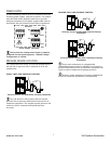
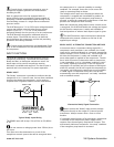


PRESSURE SENSOR CONNECTION
The pressure sensor connects to terminal X05 of the X4I
terminal PCB using a shielded 18 AWG maximum 2-
conductor cable no more than 330 feet (100 meters) in
length. The transducer threads are BPT. It is the
equivalent of ¼” NPT.
Pressure Sensor Wiring and Location
Wire polarity is important.
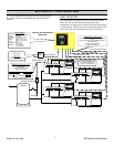
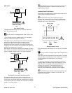
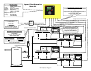
IR-PCB INTERFACE MODULE
8
The IR-PCB is designed to interface a compressor with
the X4I using a 7-conductor shielded cable or individual
wires run through grounded conduit no greater than 330
feet (100 meters) in length.
Each compressor in the system must be assigned a
unique identification number from 1 up to the number of
compressors in the system. The identification number
should be clearly indicated on each compressor for
operational reference.
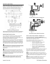
For each compressor utilizing an IR-PCB, connection to
the X4I the signal wires must be made to the correct X4I
terminals for that compressor number. Compressor 1
should be wired to terminal X01 on the terminal PCB,
Compressor 2 should be wired to terminal X02 on the
terminal PCB, etc.
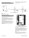
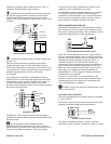
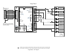
IR-PCB Interface Module
The IR-PCB is a DIN rail mountable module designed to
be installed within the compressor starter enclosure.
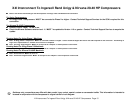
Each air compressor must be equipped with a
load/unload regulation system and, if not regulated with
a single electro-mechanical pressure switch, have a
facility for a remote load/unload control with the ability
to accept a volt-free switching contact input for remote
load/unload. Each air compressor must have Auto
Restart capability.
V
For variable speed compressor(s) equipped with a
“variable/fixed” digital input function, install a 7-
conductor shielded cable from the IR-PCB to the X4I.
www.air.irco.com X4I System Automation