


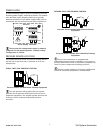
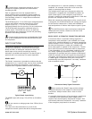

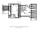
AUXILIARY OUTPUT (OPTION)
The X4I is equipped with a remote relay contact output at
terminals 33 and 34 (X08).
13
The function of the output is menu selectable and can be
adapted for differing application requirements.
X08
33
34
R6
Auxiliary Output Circuit
The remote output relay contacts are rated for 240V “CE”
/ 115V “UL” @ 5A maximum.
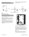
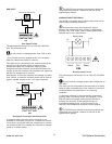
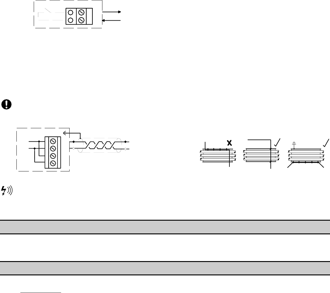
RS485 COMMUNICATIONS
The X4I is equipped with an RS485 network
communications capability using the proprietary
Multi485 protocol.
This can be only used for remote connectivity to
optional X4I expansion networked units and modules
with proprietary Multi485 communications capabilities.
28
30
27
29
L2
L1
RS485
L1
L2
X06
RS-485 Connection Circuit
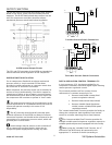
RS485 data communications and other low voltage
signals can be subject to electrical interference. This
potential can result in intermittent malfunction or
anomaly that is difficult to diagnose. To avoid this
possibility, always use shielded cables, securely bonded
to a known ground at one end. In addition, give careful
consideration to cable routing during installation.
• Never route an RS485 data
communications or low voltage signal
cable alongside a high voltage or 3-
phase power supply cable. If it is
necessary to cross the path of a power
supply cable(s), always cross at a right
angle.
• If it is necessary to follow the route of
power supply cables for a short distance
(for example: from a compressor to a
wall along a suspended cable tray),
attach the RS485 or signal cable on the
outside of a grounded cable tray such
that the cable tray forms a grounded
electrical interference shield.
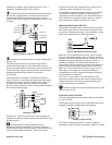
• Where possible, never route an RS485 or
signal cable near to equipment or
devices that may be a source of
electrical interference. For example: 3-
phase power supply transformer, high
voltage switchgear unit, frequency
inverter drive module, radio
communications antenna.
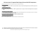
SECTION 5 — ASSISTANCE
Contacting Technical Support Services or Service Bulletins listed on the IR ServiceNet can provide further assistance if there
are other questions or concerns during Installation and Start-up. Also, additional Application and Compressor Interconnect
Guides will be posted and available on the IR ServiceNet as they are developed and created.
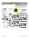
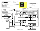
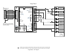
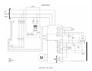
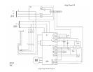
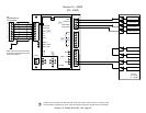
SECTION 6 — X4I OVERVIEW AND INTERCONNECT DRAWINGS
The following pages are to assist with the connection of the X4I to variety of Ingersoll Rand Compressors. These drawings
are for
Guidance Only; connections may differ with date, model, type, variant, special, custom or concession builds. This
information is intended to be used in conjunction with the compressor’s original control circuit diagram.
www.air.irco.com X4I System Automation