


KM1
0 VAC
TM2
Contact
P
To TM2 Relay
To KM2 Contact
+VDC
Load Enable
Load/Unload
VFD/fixed
IN
NO
C
NC
NO
C
NC
RUN
ALARM
READY
OUT
V
SEQ CONT
LOAD UNL
GND
D11
D12
+20V
V
1
2
3
4
5
6
2
1
LED 5 VFD
LED 2 LOAD
LED 1 SEQ
LED 4
READY
LED 3
RUN
C03
C01
C02
C04
C05
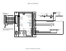
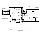
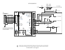
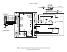
IR-PCB
1
2
3
4
5
6
V1
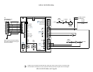
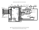
X4I
COMPRESSOR #1
X01 TERMINAL
Refer to the X4I Overview Drawing
for the X4I Compressor 2 through 4
terminal connections
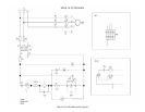
To TM3 Contact
To AS Switch
K2 Contact
TM2 Contact
SS
MOL
Contact
110VAC
ST
CR
Contact
HAT
MCB2
Contact
E-STOP
ST
(OPT)
K3
Contact
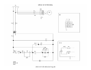
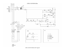
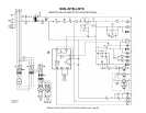
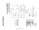
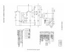
Guidance only; connections may differ with date, model, type, variant, special, custom or concession builds.
This information is intended to be used in conjunction with the compressor’s original control circuit diagram.
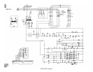
SSR M15-22c 20-30HP XF EP HP HXP 50-60Hz
SSR M15-22c 20-30HP XF EP HP HXP 50-60Hz 1of2 Page 61