


compressor number) with an additional wire. Use a 7-
conductor shielded cable in this instance.
Compressors that use electronic pressure detection
but are not equipped with a remote pressure control
enable feature will not automatically revert to local
control if the X4I is stopped or experiences a fault or loss
of power.
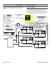
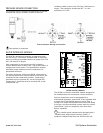
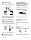
Load/Unload
+VDC
Load Enable
VFD/Fixed
ir-PCB
Load/Unload
Load Enable
VFD/Fixed
+VDC
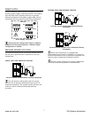
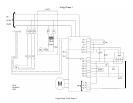
Load, Sequence, and VFD Connections
Compressor controller inputs common voltage may
be 0V or +V.
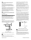
The local/remote pressure regulation input and/or
remote load input logic of some electronic pressure
sensor type controllers are reversed. In this instance, the
“pressure switch” outputs (terminal C02) can be used to
establish alternative logic control connections.
For Example:
If the compressor controller “Local/Remote Pressure
Control” input is a normally open type (local when open,
remote when closed), but the “Remote Load” input is a
normally closed type (load when open), the IR-PCB
pressure switch terminal contacts can be used to achieve
the correct switching logic.
C02
NO
OUT
C
NC
NO
C
NC
IN
common
common
Local/Remote
Remote Load
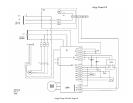
Alternate Logic
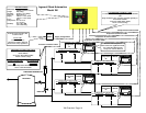
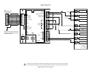
Examine the “i-PCB” internal output circuit diagram to
establish any desired switching logic that may differ from
normal practice.
Do not attempt to utilize “Digital Pressure
Regulation Control” (terminal C01) and the “Pressure
Switch Control” (terminal C02) output connections at the
same time for different products. These two output
functions are internally connected and a short circuit
condition and/or malfunction may result.
The IR-PCB connection examples shown in this manual
are intended to provide a guide for the majority of
compressor control systems in use. Some compressors
have variations in operation and/or function; consult
your compressor supplier/specialist for advice.
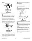
SERVICE MAINTENANCE SWITCH
The IR-PCB is equipped with a volt-free input (terminal
C05) that can be used to remove the compressor from
X4I control, without generating a fault condition, during
short-term maintenance or servicing periods.
1
2
C05
Service Maintenance Switch Circuit
When the “Service Maintenance Switch” input terminal
pins are connected together using a volt-free switching
contact, the X4I will indicate that the compressor is not
available but will not generate a warning, alarm, or
shutdown condition. The X4I will also remove the
compressor from the sequence strategy and substitute
with an alternative available compressor if necessary.
When the “Service Maintenance Switch” input circuit is
open again, the compressor will automatically be
accepted back in to the sequence strategy and will be
utilized when next required.
The use of a “key switch” is recommended for this
purpose in order to prevent the switch contacts being
inadvertently left in the closed circuit condition after
service maintenance is complete.
DO NOT connect any external voltage source to the
pins of terminal C05.
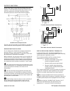
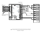
AUXILIARY INPUT (OPTION)
The X4I is equipped with an auxiliary input at terminals
31 and 32 (X07).
The function of the input is menu selectable and can be
adapted for differing application requirements.
31
X07
32
Auxiliary Input Circuit
The input is designed to detect a remote “volt-free”
switching contact (rated for a minimum 24VDC @ 10mA).
12
www.air.irco.com X4I System Automation