


+VDC
Load Enable
Load/Unload
VFD/fixed
IN
NO
C
NC
NO
C
NC
RUN
ALARM
READY
OUT
V
SEQ CONT
LOAD UNL
GND
D11
D12
+20V
V
1
2
3
4
5
6
2
1
LED 5 VFD
LED 2 LOAD
LED 1 SEQ
LED 4
READY
LED 3
RUN
C03
C01
C02
C04
C05
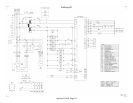
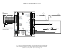
IR-PCB
1
2
3
4
5
6
V1
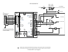
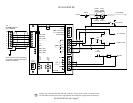
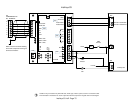
X4I
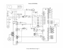
COMPRESSOR #1
X01 TERMINAL
Refer to the X4I Overview Drawing
for the X4I Compressor 2 through 4
terminal connections
1
2
3
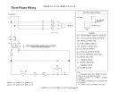
110VAC
E-STOP
Redeye
BTS2-
HATS
34
33
32
9
10
11
Redeye
BTS1-
SE
DSA
J5
SE
ESA/UP
J5
34 36
7
3
2
1
SG
P2
SG
P1
1
5
4
6
7
3
2
1
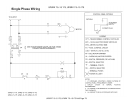
N
H
110 VAC
Supply
Hot
Neutral
Neutral
Remote Load / Unload
Run
Remote Load Enable
COM
COM
SE
ESA/UP
J5
SE
DSA
J5
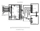
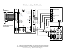
Intellisys Controller
Sequence Interface 1
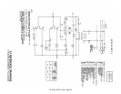
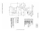
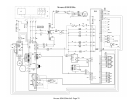
Guidance only; connections may differ with date, model, type, variant, special, custom or concession builds.
This information is intended to be used in conjunction with the compressor’s original control circuit diagram.
SI1 Interface to Redeye, SE, SG Controllers
SI1 Interface to Redeye, SE, SG Controllers Page 73