


Consult the air compressor manual or your air
compressor supplier/specialist for details before
installing the X4I.
Each air compressor must be equipped with an
online/offline pressure regulation system capable of
accepting a remote load/unload signal through a volt
free switching contact or a single electro-mechanical
pressure switch.
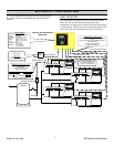
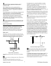
The IR-PCB accepts a 12V to 250V input voltage detection
system and utilizes universal relay contact control
outputs (250V “CE” / 115V “UL” @ 5A maximum)
integrated directly into the circuits of an air compressor.
The IR-PCB avoids the need for additional relays or
remote inputs. The IR-PCB also acts as an electrical
barrier between the compressor and the X4I providing
protection and voltage isolation.
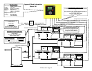
Consult the X4I Interconnect and Application Guide
prior to the installation of the X4I and the IR-PCB to the
air compressor.
INPUT FUNCTIONS
9
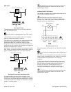
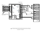
The IR-PCB is fitted with a six-pin terminal, C04, for
compressor monitoring. The IR-PCB uses two inputs,
Ready and Run, to determine compressor status. An
alarm input can be used if compressor warning
indication is available and required. The alarm input is
optional and is not necessary for system operation.
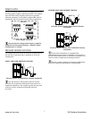
READY INPUT
The ‘Ready’ connection is intended to indicate that the
compressor is in a “started” state, has no alarm condition
that has shut down the compressor, and is ready to
respond to X4I regulation without manual intervention.
0V
+V
READY LAMP
RUN
READY
ALARM
C04
Typical Ready Input Wiring
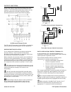
The READY input will accept 12V to 250V ac (50/60Hz)
or dc.
Do not connect a voltage greater than 250Vac/dc to
this input.
This input must be connected to a circuit of the
compressor control system that will be energized when
the compressor is in a started (standby or running)
condition. For example, locate the circuit across the
ready or operating lamp as shown.
The voltage to this input must de-energize when the
compressor is stopped and unavailable to produce air
upon a load signal, or the emergency stop button is
pressed, or when the compressor experiences a fault that
prevents the compressor from running.
When the compressor ready lamp or other control circuit
is energized, the IR-PCB will detect the voltage and signal
the X4I that the compressor is ready and available to
load and produce air when a load request signal is given.
The IR-PCB common input terminal must always be
connected to the neutral, common or 0V line of the
applied input voltage.
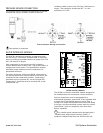
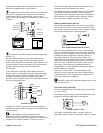
READY INPUT, ALTERNATIVE CONNECTION METHOD
In instances where a convenient voltage signal for a
compressor ready condition is not available, the “ready”
input can be connected directly to a constant compressor
control voltage (12V to 250Vac or dc). This will signal the
X4I that the compressor is ready and available at all
times when power is applied to the compressor. The X4I
has a built-in function to determine when a compressor
is not responding, or is in a shutdown condition, even if
the “ready” signal says otherwise. If the X4I requests a
compressor to run/load, but fails to detect a RUN signal
within 60 seconds, the X4I will regard the compressor as
“not ready” and indicate the compressor as not available.
If a RUN signal is reacquired at any time, the X4I will
automatically reset the compressor “not ready” condition
and re-establish control.
F1
+Vac
0Vac
READY
Alternative Ready Signal Connection
Never connect the “Ready” input positive voltage
connection directly to the output of a control system
transformer. Always connect after a fuse or circuit
breaker.
If a normally closed contact of an emergency stop button
is included in the compressor power supply circuit,
connect after the emergency stop button contacts. This
will instantly indicate a compressor “not ready” condition
if the emergency stop button is activated.
www.air.irco.com X4I System Automation