


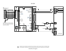
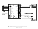
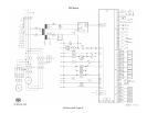
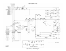
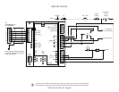
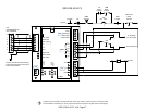
KM1
0 VAC
KM1 Relay
Contact
KM1
Relay
Contact
TM3
Relay
Contact
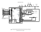
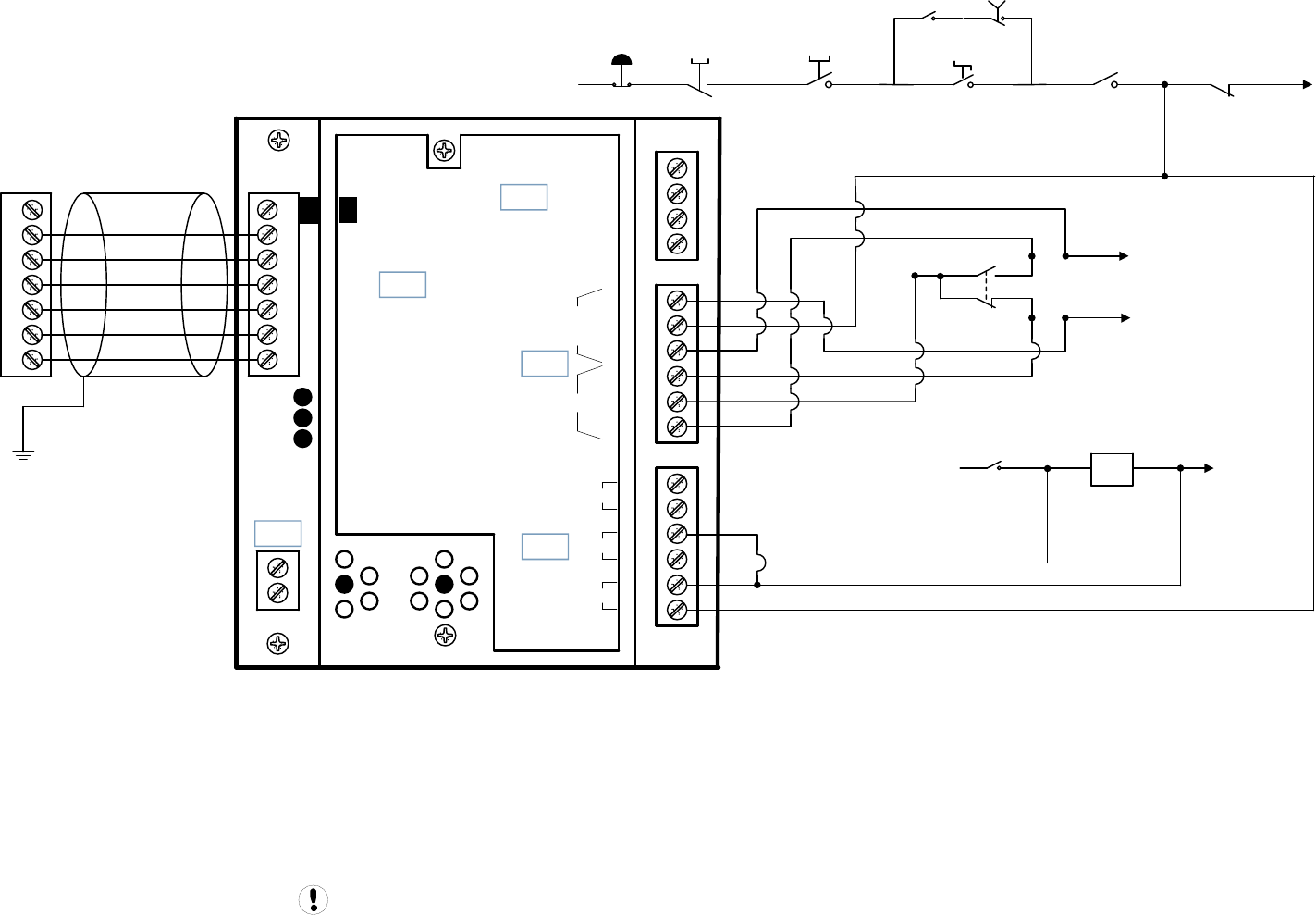
Guidance only; connections may differ with date, model, type, variant, special, custom or concession builds.
This information is intended to be used in conjunction with the compressor’s original control circuit diagram.
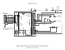
+VDC
Load Enable
Load/Unload
VFD/fixed
IN
NO
C
NC
NO
C
NC
RUN
ALARM
READY
OUT
V
SEQ CONT
LOAD UNL
GND
D11
D12
+20V
V
1
2
3
4
5
6
2
1
LED 5 VFD
LED 2 LOAD
LED 1 SEQ
LED 4
READY
LED 3
RUN
C03
C01
C02
C04
C05
IR-PCB
1
2
3
4
5
6
V1
X4I
COMPRESSOR #1
X01 TERMINAL
Refer to the X4I Overview Drawing
for the X4I Compressor 2 through 4
terminal connections
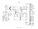
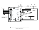
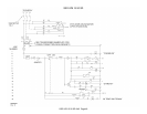
E-STOP
110VAC
HATR
Contact
Restart TD
Relay
Contact
SS
MOL
Contact
MMS
Contact
P
To TM2 Relay
To KM1 Contact
To KM2 Contact
SSR UP5 22-37 SD
SSR UP5 22-37 SD 1of2 Page 41