


TP-6880 10/14 13Section 1 Descriptions and Service Views
Section 1 Descriptions and Service Views
1.1 Introduction
The generator set specification sheets provide specific
generator and engine information. Refer to the spec
sheet for data not supplied in this manual. Consult the
generatorsetservice manual,engineoperationmanual,
and engine service manual for additionalspecifications.
Obtain copies of the latest spec sheets, manuals,
diagrams, and drawings from your local distributor/
dealer.
1.2 Engine
The 8RESV generator set has a four-cycle, single
cylinder, air-cooled Kohlerr engine and 10/12RESV
generator sets have a four-cycle, twin cylinder,
air-cooled Kohlerr engine. The engines operate on
clean-burning natural gas or LPG. Engine features
include:
D Efficient overhead valve design and full pressure
lubrication for maximum power, torque, and reliability
under all operating conditions.
D Dependable, maintenance-free electronic ignition.
D Precision-formulated cast iron construction of parts
subjected to the most wear and tear.
D Field-convertible multi-fuel systems that allow fuel
changeoverfrom naturalgasto LPG(andvice- versa)
while maintaining EPA emission certification.
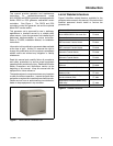
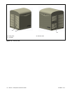
1.3 Generator Set Enclosure
Thegenerator setishoused inasteel enclosurewhichis
dipped in e-coat for extra corrosion protection and
painted with a durable powder coat finish. The
enclosure has a hinged, locking roof that allows easy
access to the generator set controller when required,
but locks securely to prevent unauthorized access.
To open the roof, insert the tool provided with the
enclosure and turn counterclockwise 1/4 turn. Then just
raise the roof. The roof stays open until you are ready to
close it.
Be sure to close and lock the enclosure, and keep the
tool in a secure location.
1.4 Alternator
The generator uses Kohler’s unique PowerBoostt
voltage regulation system, which provides instant
response to load changes.
PowerBoostt ensures reliable motor starting and
consistent voltage levels. PowerBoostt utilizes a
voltage excitation system that employs a winding
independent of the main output windings to provide
excitation voltage.
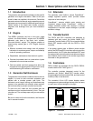
1.5 Transfer Switch
The RDC2 and DC2 controllers are designed to
interface with and control the Kohler Model RXT
Automatic Transfer Switch (ATS). Do not use the Kohler
Model RRT transfer switch with t he RDC2 or DC2
controller.
If the power system uses a different model transfer
switch,theRDC2 andDC2controllers willnotcontrolthe
transfer switch. An ATS other than the Model RXT must
be equipped with atransfer switch controller and engine
start contacts that connect to the remote engine start
terminals on the generator set.
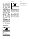
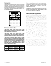
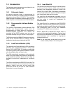
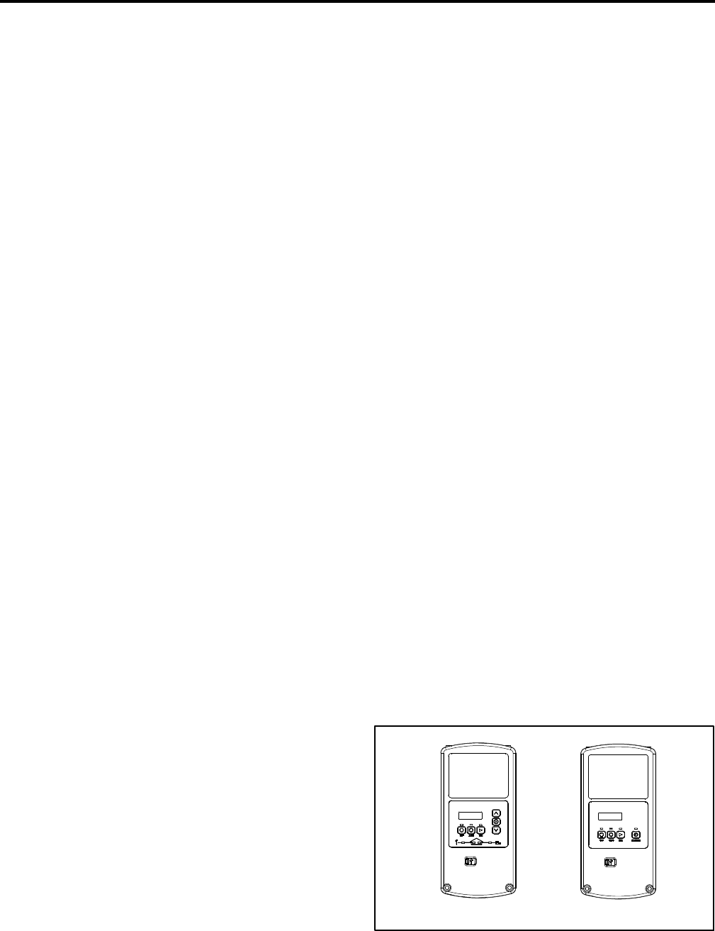
1.6 Controllers
RESV models are equipped with the RDC2. RESVL
models use the DC2. See Figure 1-1.
The controller provides integrated control for the
generator set, Kohlerr Model RXT transfer switch,
programmable interface module (PIM), and load control
module (LCM) or load shed kit.
The controller’s 2-line LCD screen displays status
messages and system settings that are clear and easy
to read, even in direct sunlight or low light.
RDC2 (RESV) DC2 (RESVL)
Figure 1-1 Controllers