


TP-6880 10/1466 Section 5 Scheduled Maintenance
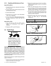
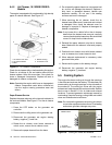
5.4.2 Air Cleaner, 10/12RESV/RESVL
Models
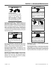
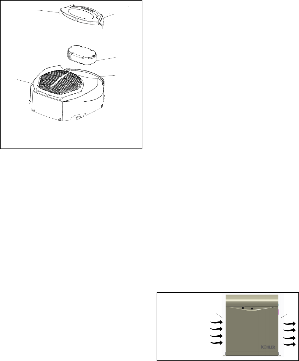
The engine is equipped with a replaceable, high density
paper air cleaner element. See Figure 5-7.
tp6515
1. Air cleaner cover lever
2. Air cleaner element
3. Base
4. Blower housing
5. Air cleaner cover
2
3
1
4
5
Figure 5-7 Air Cleaner Components
Check theair cleaner daily or before starting the engine.
Check for a buildup of dirt and debris around the air
cleaner system. Keep this area clean. Also check for
loose or damaged components. Replace all bent or
damaged air cleaner components.
Note: Operating the engine with loose or damaged air
cleaner components could allow unfiltered air
into the engine causing premature wear and
failure.
Paper Element Service
Replace the paper element at the intervals indicated in
the service schedule. See Figure 5-7 for the air cleaner
components.
1. Press the OFF button on the generator set
controller.
2. Disconnect the utility power to the generator set.
3. Disconnect the generator set engine starting
battery, negative (--) lead first.
4. Rotate the air cleaner cover levers outward to
unlock cover; remove the air cleaner cover.
5. Remove the paper element from the base.
6. Do not wash the paper element or use pressurized
air, as this will damage the element. Replace a
dirty, bent, or damaged element. Handle new
elements carefully; do not use if the sealing
surfaces are bent or damaged.
7. When servicing the air cleaner, check the air
cleaner base. Make sure it is secured and not bent
or damaged. Also, check the element cover for
damage or improper fit. Replace all damaged air
cleaner components.
Note: If any loose dirt or debris fell on the air cleaner
base when the element was removed, carefully
removeit andwipe thebase clean.Becareful that
none of it drops into the intake throat.
8. Reinstall the paper element onto the air cleaner
base. Make sure the element is flat and properly
seated.
9. Position the air cleaner cover with levers outward
over air cleaner; turn levers inward to lock.
10. When element replacement is necessary, order
genuine Kohler parts.
11. Reconnect the power to the battery charger.
12. Reconnect the generator set engine starting
battery, negative (--) lead last.
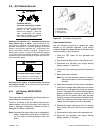
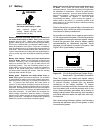
5.5 Cooling System
The engine fan draws cooling air through the openings
in the sides and end near the battery. The alternator fan
draws cooling air through openings on the side walls of
the enclosure. The cooling air mixes with the engine
exhaust andis discharged atthe exhaust outlet. Seethe
service view in Section 1.9 for air intake and exhaust
locations. To prevent generator set damage caused by
overheating, keep the housing cooling inlets and outlets
clean and unobstructed at all times.
Note: Do not block thegenerator set coolingair inlets or
mount other equipment above them. Overheating
and severe generator damage may occur.
1. Air intake
2. Exhaust outlet
1
2
FRONT VIEW
Figure 5-8 Cooling Air Intake and Exhaust