TP-6880 10/1432 Section 3 RDC2 Controller Operation
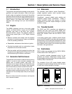
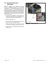
3.3 Controller Power
The RDC2 controller is powered by the generator set
engine starting battery and the built-in battery charger.
Note: To disconnect controller power, disconnect the
utility power to the generator set and disconnect
the battery .
If controller power is disconnected and reconnected,
you willbe prompted to setthe time, date,and exerciser.
The first setting will flash. Press the Up and Down arrow
buttons to change the setting. Press Select to save the
setting and move on to the next. Repeat until all settings
are saved and the controller returns to the main menu.
See Section3.5 formore detailed instructionsto change
settings on theRDC2. See Section3.6 formore detailed
instructions to set the exerciser or change the exercise
settings.
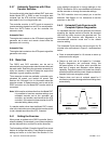
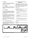
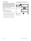
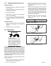
3.4 Battery Charging
The controller includes a built-in battery charger to
maintain the engine starting battery. The RDC2
controller monitors the battery voltage and provides a
constant 14.0 ±2% VDC voltage and maximum 2.5
amps to charge the battery.
The installer must connect 120 VAC/60Hz utility power
providedfrom thebuilding ona breaker-protectedcircuit
for the built-in battery charger.
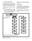
3.5 Changing Settings
Some settings can be changed from the controller
keypad.The controllersettings andgeneratorset output
are factory-set and should not require field adjustment
under normal circumstances. Check and adjust the
settings and/or output when:
D The controller has been replaced.
D The voltage requires adjustment for a particular
application.
D Troubleshooting generator set problems.
Havecontroller setupand adjustmentperformedonlyby
an authorized Kohler distributor/dealer or authorized
representative.
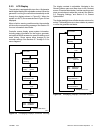
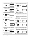
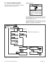
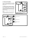
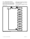
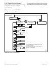
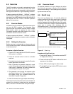
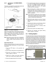
The following procedure explains how to change
settings. See Figure 3-7 for an example using the Date
and Time settings.
Note: Use caution when navigating the controller
menus. In some menus, pressing the Select
button can enable editing of the controller
settings. Changing the settings to incorrect
values can adversely affect generator set
operation or render the unit inoperable.
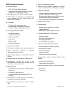
Procedure to Change Settings
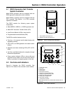
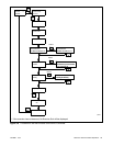
1. Press the Select button to enter the main menu.
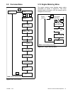
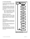
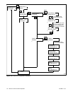
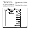
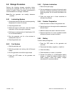
2. Pressthedownarrow buttonuntilthedesired menu
is displayed. The Genset System menu is used for
this example. See Figure 3-9.
3. Press the Select button to enter the genset system
displays. See Figure 3-7.
4. Press the down arrow button to step through the
generator set system settings.
5. Tochange anyof thegenset systemsettings,press
the Select button. The selected setting flashes.
6. Press the up or down arrow buttons to increase or
decrease the setting.
7. When the desired setting is shown, press Select.
The value stops flashing. If there are additional
adjustable settings on the screen, the next setting
flashes. For example, in the date menu, the day,
month, and year can be adjusted.
8. Repeat steps 6 and 7 for each setting on the
screen.
9. Press the down arrow to step to the next screen.
10. To exit, press the down arrow button until Return is
displayed.Press theSelectbutton toexit themenu.
11. Press the AUTO or OFF button to exit the main
menu.
Note: If no buttons are pushed, the controller exits the
menus and returns to the generator set status
display after 5 minutes.