TP-6880 10/14 21Section 2 Generator Set Operation
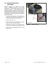
2.2 Exercising the Generator Set
Operate the generator set without load once each week
for 20 minutes. See Section 2.4 for information about
loaded and unloaded exercise modes. For instructions
to set the exerciser, see:
D Section 3.6 for the RDC2 controller
D Section 4.5 for the DC2 controller
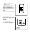
2.3 Generator Set Operation
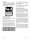
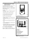
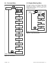
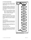
2.3.1 Local Starting and Stopping
Start: Press the RUN button to immediately start the
generator set.
Stop: Press the OFF button. The engine stops.
Run the generator set with no load for at least 2 minutes
to ensure adequate engine cooldown.
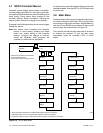
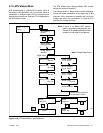
2.3.2 Automatic Starting and Stopping
An automatic transfer switch monitors the utility power
and signals the generator set to start when utility power
is lost. The ATS then transfers the load to the generator
set.
When utility power is restored, the transfer switch
transfers the load back to utility, runs the generator set
with no load to cool down the engine, and then stops the
generator set.
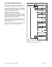
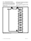
2.3.3 Remote Starting and Stopping
A remote switch connected to terminals 3 and 4 can be
used to start and stop the generator set. Close the
switch to start and run the generator set. Open the
switch to stop the generator set.
Run the generator set with no load for at least 2 minutes
to ensure adequate engine cooldown.
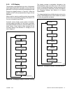
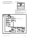
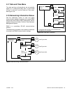
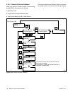
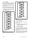
2.3.4 Engine Start Crank Cycle
The controller attempts to start the generator set three
times (three crank cycles, 15 seconds crank and
15 seconds off). If the generator set does not start in
three attempts, the system shuts down on an overcrank
fault. See Section 2.5.
Cranking 1, 2, and 3 are displayed during the crank
cycle. Pressing the OFF button during the crank cycle
stops the cranking. No other buttons are acknowledged
during the crank cycle.
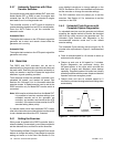
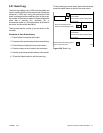
2.3.5 Engine Cooldown
The engine cooldown time delay allows the engine to
run after the loads have been removed.
The engine cooldowntime delay is set to 5 minutes.The
engine stops before the cooldown time delay expires if
the temperature drops below the cooled-down
temperature level, or if the temperature rises above the
high limit during the cooldown cycle.
If a transfer switch other than the Model RXT is used, an
additional engine cooldown time delay may be
programmed on the transfer switch. To allow the smart
engine cooldown on the RDC2/DC2 controller to
operate most efficiently, set the cooldown time on the
transfer switch controller to zero or the minimum time
allowed. Refer to the instructions provided with the
transfer switch for more information.
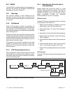
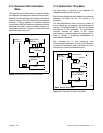
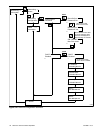
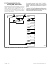
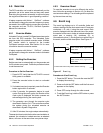
2.3.6 Automatic Operation with Model
RXT Transfer Switch
The Model RXT transfer switch connects to the
RDC2/DC2 controller through the ATS interface board
on the transfer switch. Alsosee the Model RXT Transfer
Switch Operation/Installation Manual for more
information about transfer switch operation.
The controller must be in AUTO mode for automatic
transfer switch operation.
Automatic Start
TheRDC2/DC2controller receivesutilitysourcevoltage
sensing data from the Model RXT transfer switch.
1. If the utility source voltage falls below an
acceptable level, the controller starts the engine
start time delay.
2. If the utility source is not restored before the time
delay expires, the generator set starts.
3. After the Normal-to-Emergency time delay, the
ATS is signaled to transfer the load to the
emergency source.
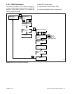
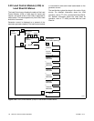
Automatic Stop with Engine Cooldown
1. When the utility source is restored, the
Emergency-to-Normal time delay starts.
2. When the Emergency-to-Normal time delay
expires, the load is transferred to the utility.
3. The generator set runs through the engine
cooldown cycle and then stops.