


TP-6880 10/14 41Section 3 RDC2 Controller Operation
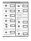
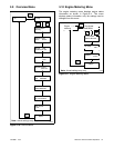
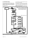
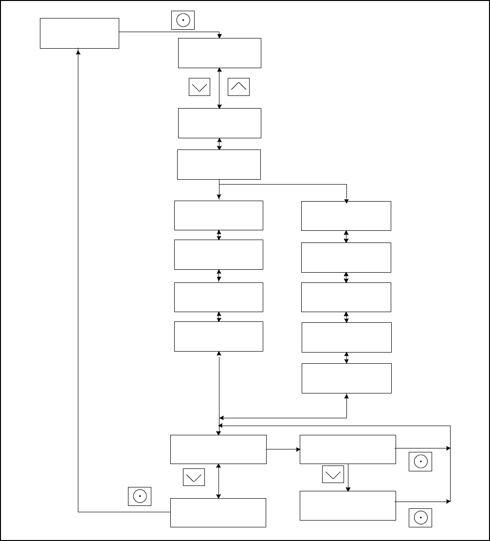
3.15 ATS Status Menu
ATS menus appear if a Model RXT transfer switch is
connected to the generator set. If no transfer switch is
connected, or another model ATS is connected to the
engine start connections, Remote ATS is displayed on
the ATS Status screen.
The ATS Status menu displays Model RXT transfer
switch and source information.
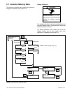
The voltage shown in these menus can be calibrated.
Follow the safety precautions at the beginning of this
manuals. Use a voltmeter to measure the line-to-line
voltage and follow the instructions in Figure 3-16 to
calibrate the voltage readings.
Emerg Volts:
tp6810
Normal Voltage:
L1--L2 240 V
Normal Voltage:
L2--L3 240 V
Normal Voltage:
L3--L1: 240 V
ATS - --->
Status
Normal Freq.:
60.0 Hz
ATS Position:
Normal
Normal Status:
Not/Acceptable
Emerg. Status:
Standby
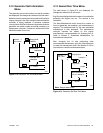
Three-phase
Single-phase
Reset
Calibration
<---- Return
Reset
Calib? No
Reset
Calib? Yes
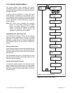
Note: If there is no Model RXT transfer
switch connected to the generator set,
RemoteATSis displayedandthe other
screens on this page do not appear.
Normal Freq.:
60.0 Hz
Normal Volts:
240.0 V
Emerg. Freq.:
60.0 Hz
240.0 V
Similar screens appear for
the emergency source.
Normal Rotation:
Note: Sample data shown.
Figure 3-16 ATS Status Menu, with Calibration