


A-3
INSTALLATION
LN-742 & LN-742H
A-3
4. Connect the remaining end of the control cable
with the eight-socket cable plug to the mating
receptacle on the LN-742.
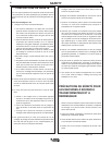
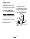
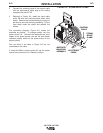
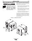
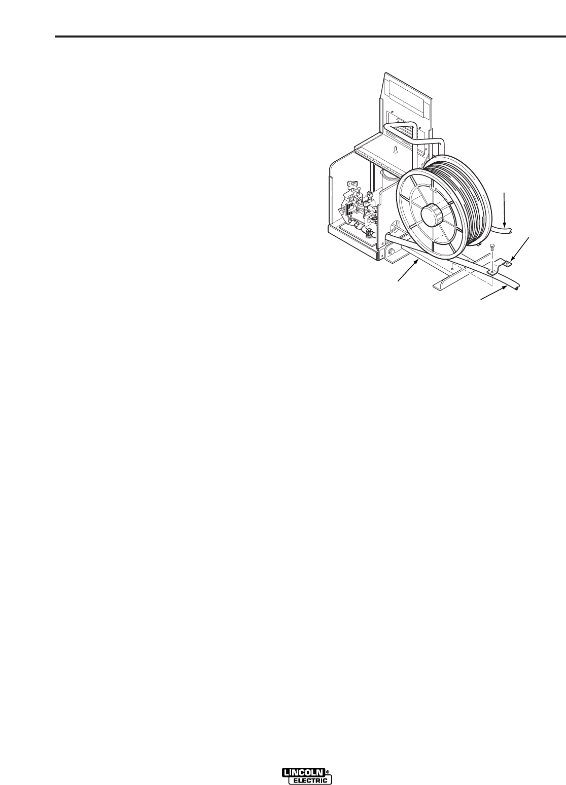
5. Referring to Figure A.2, install the input cable
under the wire reel mounting stand strain relief
clamp. Remove the screws holding the clamp to
the base of wire reel mounting assembly. Put the
input cable under the clamp and reinstall the
screws.
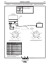
The connection diagram, Figure A.3, shows the
electrode as positive. To change polarity, turn the
power source off. Reverse the electrode and work
cables at the power source, and set the wire feeder
voltmeter polarity switch on the power source to the
proper polarity.
Pins not listed in the table in Figure A.3 are not
connected on the cable.
If using the K589-1 remote control kit, set the power
source control switch to the “Remote” position.
WIRE REEL
MOUNTING
ASSEMBLY
CONTROL
CABLE
ELECTRODE
CABLE
STRAIN
RELIEF
CLAMP
FIGURE A.2 – STRAIN RELIEF CLAMP.