


B-2
OPERATION
B-2
• 0.045 to 5/64 in. (1.2 to 2.0 mm) cored wire for
Innershield processes.
The LN-742H is capable of the following wire feed
ranges:
• 0.025 to 0.045 in. (0.6 to 1.2 mm) solid wire for gas-
metal-arc or CV submerged arc processes.
• 0.035 to 0.045 in. (1.2 mm) cored wire for
Outershield, Metalshield or Innershield processes.
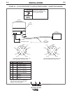
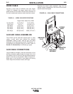
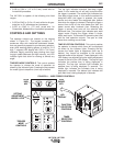
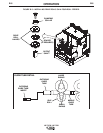
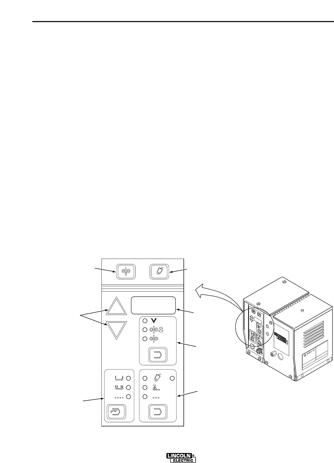
CONTROLS AND SETTINGS
The operator controls are located on the keypad
shown in Figure B.1. The keypad consists of: 7
membrane keys with tactile-feel embossed domes,
that are generously spaced to provide easy selection,
even while wearing welding gloves; a long-life, 3-1/2
digit, 7 segment LED display with 0.56 in. (14.2 mm)
character height, permitting easy viewing even from
long gun cable distances; and high intensity, red, LED
indicator lights that allow for viewing at almost any
angle.
TRIGGER MODE CONTROLS. This control enables
the operator to choose the mode of operation as
shown by the indicator lights. Pressing the key causes
the mode lights to sequence (from top to bottom).
The top light indicates standard (two-step) trigger
mode. In this mode the unit will only be active when
the trigger is pressed. The middle light indicates lock
(four-step) trigger mode. In this mode the solenoid is
energized when the trigger is pressed, the power
source and wire feeder are energized after preflow
time when the trigger is released. Closing the trigger a
second time turns off the wire feeder and then the
power source after burnback time. Releasing the
trigger a second time turns off the solenoid after
Burnback time. The bottom light indicates spot weld
trigger mode. Closing the trigger allows a single,
timed, weld cycle. The duration of the weld cycle is set
with the time selection controls. The spot on timer
starts when welding current flows.
TIME SELECTION CONTROLS. This control enables
the operator to choose which timer will be displayed
as shown by the indicator lights. Pressing the key
causes the mode lights to sequence (from top to
bottom). Any timers not available to the currently
selected mode will be skipped. Times displayed in the
LED display are adjusted using the setting adjustment
arrows to the left of the LED display. The top left light
indicates the preflow time is being displayed in
seconds. The top right indicator light indicates the
postflow time is being displayed in seconds. The
middle light indicates the burnback time is being
displayed in seconds. The bottom light indicates the
spot weld time is being displayed in seconds.
LN-742 & LN-742H
COLD INCH
OLTMETER
INCH
WFS
PREFLOW POSTFLOW
BURNBACK
SPOT
STD
LOCK
SPOT
TIMETRIGGER MODE
t1
t2
GAS PURGE
t
t
t
GAS
PURGE
KEY
LED
DISPLAY
FUNCTION
SELECTION
CONTROLS
TIMER
SELECTION
CONTROLS
SETTING
ADJUSTMENT
ARROW KEYS
TRIGGER
MODE
CONTROLS
COLD
INCH
KEY
FIGURE B.1 – WIRE FEEDER CONTROLS.