


A-2
INSTALLATION
LN-742 & LN-742H
A-2
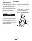
MOUNTING LOCATION
The LN-742 wire feeders can be mounted directly on
top of the power source providing that it is secure and
level. The LN-742 can also be mounted to an
undercarriage when portability is required. The LN-742
should be installed upright on a horizontal surface.
A K178-1 mounting platform is available for mounting
the LN-742 to the top of Idealarc power sources. Refer
to Section C, Accessories, for details.
INPUT CABLE CONNECTIONS
Refer to Section C, Accessories, for descriptions of
the various input cable assemblies available for the
LN-742 wire feeder.
Turn input power off before connecting the LN-742
wire feeder.
------------------------------------------------------------------------
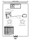
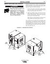
For connecting an LN-742 to a specific Lincoln power
source, follow steps 1 through 5, and refer to the
connection diagram in Figure A.3. The welding cable
used must be sized according to the current and the
duty cycle of the application.
With input power disconnected at the source, install
the input cable per connection diagram A.3, and
complete the following instructions:
1. Connect the end of the control cable with the 14-
pin cable plug to the mating receptacle on the
power source.
2. Connect the electrode lead to the power source
output terminal of the desired polarity.
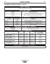
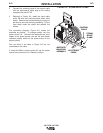
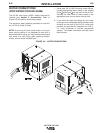
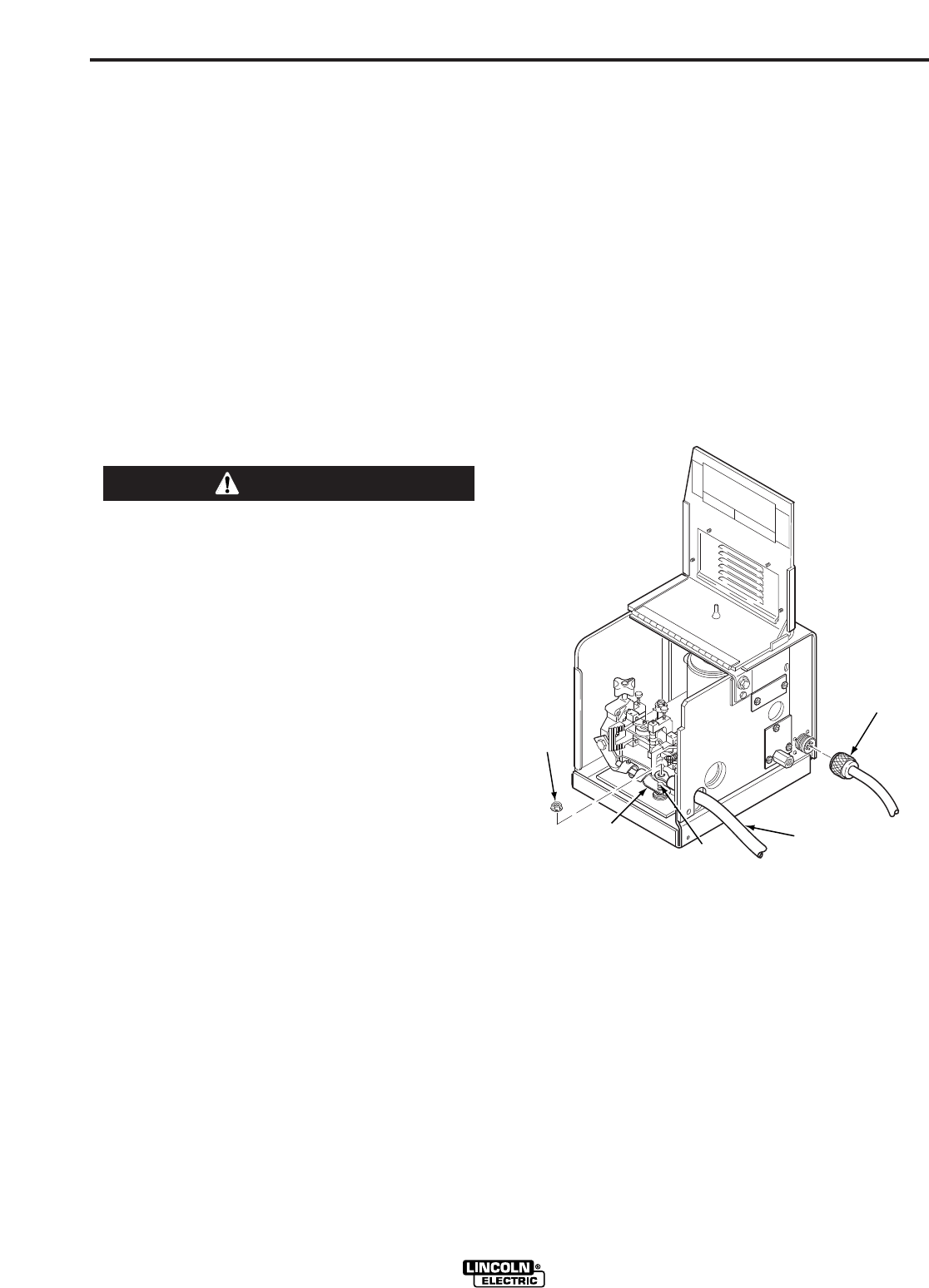
3. Referring to Figure A.1, route the other end of the
electrode cable through the large oval hole in the
rear panel of the LN-742 case. Connect the
electrode to the copper strap on the side of the
gearbox using the stud and nut provided.
FIGURE A.1 – INPUT CONTROL CABLE AND
ELECTRODE CABLE CONNECTIONS.
WARNING
NUT
STUD
ELECTRODE
CONTROL
CABLE
COPPER
STRAP