


A-5
INSTALLATION
LN-742 & LN-742H
A-5
WORK CABLE
Connect a work lead of sufficient size and length
(Table A.1) between the proper output stud on the
power source and the work. Be sure the connection to
the work makes tight metal-to-metal electrical contact.
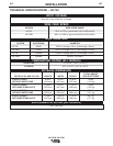
TABLE A.1 – WORK LEAD SPECIFICATIONS
Copper Work Cable Size, AWG
Current 60% Up To 50 Ft 50 Ft-100 Ft
Duty Cycle (15.2 m
2
) (15.2-30.4 m
2
)
300 Amps 0 (53 mm
2
) 00 (67 mm
2
)
400 Amps 00 (67 mm
2
) 000 (85 mm
2
)
500 Amps 00 (67 mm
2
) 000 (85 mm
2
)
600 Amps 000 (85 mm
2
) 0000 (107 mm
2
)
GUN AND CABLE ASSEMBLIES
The LN-742 can be used with several guns. In most
cases, Lincoln guns and cables are shipped
assembled, ready to weld. Use the gun and cable
assembly for the electrode type (solid, Outershield , or
Innershield) and electrode size to be used. Refer to
Section C, Accessories, for different gun types.
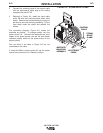
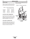
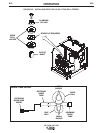
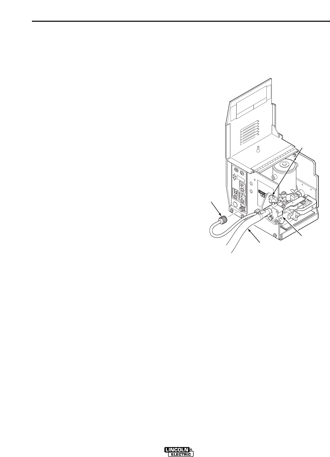
GUN CABLE CONNECTIONS
Lay the cable out straight. Insert the connector on the
welding conductor cable through the large hole in the
front panel of the LN-742 and into the brass conductor
block on the front of the gearbox. Refer to Figure A.4.
Make sure it is all the way in and tighten the locking
knob. Keep this connection clean and bright.
Connect the control cable amphenol plug into the
mating 5-cavity receptacle on the front of the control
section below the keypad.
FIGURE A.4 – GUN CABLE CONNECTIONS.
AMPHENOL
PLUG
GUN CABLE
ASSEMBLY
CONDUCTOR
BLOCK
LOCKING
KNOB