


B-5
OPERATION
B-5
3. Remove the hex head screw and clamping collar.
Remove the drive roll from the shaft.
4. The new roll to be installed is stamped for the size
wire to be fed. An “A” after the size indicates
aluminum wire. Remove the rolls from the kit and
wipe them clean. Wipe the output shaft and locating
shoulder clean.
5. Use the clamping collar and hex head screw to
install the roll on the output shaft. Certain size drive
rolls consist of two roll halves, and may contain a
spacer. If the drive roll you are installing contains a
spacer, the spacer fits between the two halves of
the drive roll. Tighten the hex head screw.
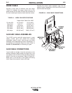
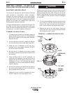
6. Back out the guide tube clamping screws.
Remove the old guide tubes, if installed.
7. Insert the longer guide tube into the rear hole and
the other guide tube through the front hole. The
fine wire chisel point end of the guide tube must
have the larger radius end next to the drive roll.
See Figure B.2. Push the guide tube back as far
as it will go and tighten the clamping screw. Insert
the incoming guide tube as far back as it will go
and tighten the clamping screw. The clamping
screws are dog points. When the guide tubes are
properly installed these dog points will lock into
the annular grooves in each of the guide tubes.
8. Set the idle roll pressure as detailed in the Idle
Roll Pressure Setting procedure detailed later in
this section.
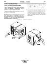
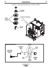
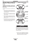
CHANGING DRIVE ROLLS FOR FOUR-
ROLL WIRE FEEDERS:
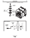
To change drive rolls on a four-roll wire feeder, refer to
Figure B.3 and perform the following steps:
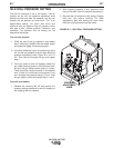
1. Turn off welding power source.
2. Remove the gun and cable from the conductor
block on the feeder by loosening the hand screw
and pulling the gun straight out of the block.
3. Open both quick release levers by moving the
levers outward and pulling them toward you.
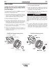
4. Loosen the thumb screws holding the guide tubes
in place. Remove the incoming and outgoing
guide tubes, if installed.
5. Remove the hex head screws and clamping
collars from the output shafts. Remove the drive
rolls and middle guide tube.
6. The new rolls to be installed are stenciled with the
wire size that will be fed. An “A” after the number
indicates aluminum wire. Remove the rolls from
the kit and wipe them clean. Wipe the output
shafts and locating shoulders clean.
7. Install one roll onto the output shaft closest to the
incoming side of the feeder clamping collar and
hex head screw. Certain size drive rolls consist of
two roll halves, and may contain a spacer. If the
drive roll you are installing contains a spacer, the
spacer fits between the two halves of the drive
roll. Tighten the hex head screw.
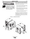
8. Install the middle guide tube, but do not tighten at
this time. When installing a 0.035” middle guide
tube the larger radius should be aligned towards
the drive roll. Slide the guide tube up against the
installed drive roll.
9. Install the second drive roll on the remaining shaft
the same way as the first. Center the middle guide
tube between the rolls and tighten the
thumbscrews holding it in place.
10. Close and latch both quick release levers.
11. Slide the longer guide tube into the rear hole of
the gearbox until it almost touches the drive roll
and guide tube. Tighten the thumbscrew to hold it
in place.
12. Install the outgoing guide tube into the front hole
of the gearbox (through the conductor block) and
tighten the thumb screw. The 0.035 in. outgoing
guide tube should have the larger radius oriented
toward the drive roll. For proper installation of the
outgoing guide tube insert, refer to Figure B.3.
13. Be certain that the guide tubes do not touch the
drive rolls or idle rolls. If they do touch, readjust
them and tighten in place.
LN-742 & LN-742H