


B-3
OPERATION
B-3
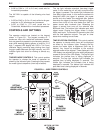
FUNCTION SELECTION CONTROLS. This control
enables the operator to select the function that will be
displayed as shown by the indicator lights. Pressing
the key causes the mode lights to sequence (from top
to bottom). Settings displayed in the LED display are
adjusted using the setting adjustment arrows to the
left of the LED display. The top light indicates the arc
voltage is being displayed in volts. The middle light
indicates the inch speed is being displayed. The
bottom light indicates the weld feed speed (WFS) is
being displayed.
INCREASE ARROW. This key increases the setting
of the parameter selected to be displayed, using the
“Quick-Set” feature for fast and accurate setting.
DECREASE ARROW. This key decreases the setting
of the parameter selected to be displayed, using the
“Quick-Set” feature for fast and accurate setting.
QUICK-SET FEATURE. This feature permits the
arrow keys to control each display digit one at a time.
The display digits blink in sequence from left to right.
Pressing an arrow key immediately after a digit blinks
alters that digit. Releasing the arrow key causes the
left-to-right sequencing to resume.
COLD INCH KEY. This key energizes the wire feeder
to inch the wire forward, but does not energize the
power source or solenoid valve.
GAS PURGE KEY. This key energizes the solenoid
valve to purge any remaining gasses, but does not
energize the wire feeder or power source.
ACCELERATION SETTING
Pressing both the Gas Purge key and the Function
Selection key at the same time, on the keypad shown
in Figure B.1, enables the acceleration setting display.
The LED display will indicate “A-X” with “X” being a
number from 1 (slowest) to 5 (fastest). This number is
adjusted using the setting adjustment arrow keys. To
exit the acceleration setting function, press both keys a
second time, or press any other key except for the
setting adjustment arrow keys.
ENGLISH OR METRIC SPEED
DISPLAY UNITS
Pressing both the Gas Purge key and Timer Selection
key causes the speed display units to toggle between
inches per minute (no decimal point displayed) or
meters per minute (decimal point displayed). If the LED
display is showing the voltmeter or one of the timer
settings when these keys are pressed, the display will
change to the weld speed to indicate the selected
speed display units. See Figure B.1 for key locations.
CIRCUIT PROTECTION
The LN-742 has solid-state overload protection of the
wire drive motor. If the wire drive motor becomes
overloaded for an extended period of time, the
protection circuitry turns off the power source, wire
feeder, and solenoid, then displays the error code E30
on the LED display. This indicates the wire drive motor
is overloaded, with the number indicating the time
remaining in seconds before the unit will automatically
reset. This number continues to decrement every
second until it reaches zero. At that time the unit
resets automatically and the previous display will
return indicating that the unit is ready for operation.
Over loads can result from: improper tip size, liner,
drive rolls, or guide tubes; obstructions or bends in the
gun cable; feeding wire that is larger than the rated
capacity of the feeder; or any other factors that would
impede normal wire feeding.
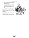
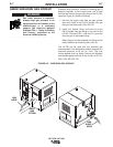
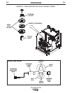
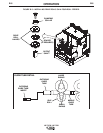
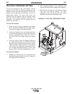
DRIVE ROLL INSTALLATION
CHANGING DRIVE ROLLS FOR TWO-
ROLL WIRE FEEDERS:
To change drive rolls on a two-roll wire feeder, refer to
Figure B.2 and perform the following steps:
1. Turn off the welding power source.
2. Rotate the latch knob on the quick release arm.
LN-742 & LN-742H