


A-3
INSTALLATION
PRECISION TIG 275
A-3
SAFETY PRECAUTIONS
SELECT SUITABLE LOCATION
Place the welder where clean cooling air can freely cir-
culate in through the top rear vents and out through the
bottom rear vents. Dirt, dust or any foreign material
that can be drawn into the welder should be kept at a
minimum. Failure to observe these precautions can
result in excessive operating temperatures and nui-
sance trips.
GRINDING
Do not direct grinding particles towards the welder. An
abundance of conductive material can cause mainte-
nance problems.
STACKING
The Precision TIG 275's cannot be stacked .
UNDERCARRIAGE LIFTING AND MOVING
When the Precision TIG 275 is purchased as a weld-
ing package, or used with any of the available
Undercarriage optional accessories, proper installation
makes the Precision TIG 275 lift bale nonfunctional.
Do not attempt to lift the power source with an under-
carriage attached. The undercarriage is designed for
hand moving only; mechanized movement can lead to
personal injury and/or damage to the Precision TIG
275.
TILTING
Each machine must be placed on a secure, level sur-
face, either directly or on a recommended undercar-
riage. The machine may topple over if this precaution
is not followed.
ENVIRONMENTAL RATING
Precision TIG 275 power sources carry an IP21S
Environmental rating. They are rated for use in damp,
dirty rain-sheltered environments.
MACHINE GROUNDING AND HIGH FRE-
QUENCY INTERFERENCE PROTECTION
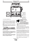
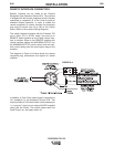
The frame of the welder must be grounded. A ground screw
marked with the symbol is located on the input connection
panel (Figure A.1) for this purpose. See your local and nation-
al electrical codes for proper grounding methods.
The spark gap oscillator in the high frequency genera-
tor, being similar to a radio transmitter, can be blamed
for many radio, TV and electronic equipment interfer-
ence problems. These problems may be the result of
radiated interference. Proper grounding methods can
reduce or eliminate radiated interference.
The Precision TIG 275 has been field tested under rec-
ommended installation conditions and has been found
to comply with F.C.C. allowable radiation limits. This
welder has also been found to comply with NEMA stan-
dards for high frequency stabilized power sources.
Radiated interference can develop in the following four
ways:
• Direct interference radiated from the welder.
• Direct interference radiated from the welding leads.
• Direct interference radiated from feedback into the
power lines.
• Interference from re-radiation of "pickup" by
ungrounded metallic objects.
Keeping these contributing factors in mind, installing
the equipment per the following instructions should
minimize problems:
1. Keep the welder power supply lines as short as
possible. Input leads within 50 feet (15.2 m) of the
welder should be enclosed in rigid metallic conduit
or equivalent shielding. There must be good electri-
cal contact between this conduit and the welder.
Both ends of the conduit must be connected to a
driven ground and the entire length must be contin-
uous.
2. Keep the work and electrode leads as short as pos-
sible and as close together as possible. Lengths
should not exceed 25 feet (7.6 m). Tape the leads
together when practical.
Read entire installation section before starting
installation.
ELECTRIC SHOCK can kill.
• Only qualified personnel should
perform this installation.
• Turn the input power OFF at the
disconnect switch or fuse box
before working on this
equipment.
• Do not touch electrically hot
parts.
• Always connect the Precision TIG 275 grounding screw (behind
the reconnect panel cover located near the back of the left case
side) to a good electrical earth ground.
• Always connect the Precision TIG 275 to a power supply
grounded in accordance with the National Electrical Code and
all local codes.
WARNING