


A-8
INSTALLATION
PRECISION TIG 275
A-8
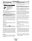
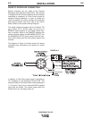
ROBOTIC INTERFACE CONNECTION
Robotic interface can be made at the Remote
Receptacle (See Operation Section B-2). The machine
is shipped with the remote receptacle circuit internally
connected to receptacle J5 of the Control board for
standard Amptrol operation. In order to enable the
remote receptacle for robotic interface its connection
plug must be moved from J5 to J5A on the Control
board. (Refer to the machine Wiring Diagram.)
The robotic interface functions with the Precision TIG
set to either TIG or STICK mode, but must be in
REMOTE switch position for the Preset Control inter-
face to function. When in the REMOTE position with
robotic interface neither the MAXIMUM OUTPUT nor
the MINIMUM OUTPUT panel controls limit the inter-
face control setting over the rated output range of the
machine.
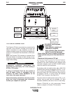
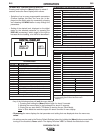
The diagram in Figure A.4 below shows the remote
receptacle plug connections and signals for robotic
interface:
In addition; a Peak Pulse output signal is provided at
J21 receptacle on the Advanced Control PCB. This
output provides a 0.2A rated switch circuit between pin
1 (+) and pin 2 (com) for an external 40VDC supplied
relay (with coil diode). This switch closes when the
Peak Pulse is on, and opens when off.
FIGURE A.4