


A-5
INSTALLATION
PRECISION TIG 275
A-5
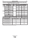
Recommended Cable Sizes for Combined Lengths of
Copper Work and Electrode Cables using 75
o
C Wire:
Machine Rating 0 to 100 Ft. 101 to 200 Ft 201 to 250 Ft
275A/40% #1 (42.4 mm
2
) 1/0 (53.5 mm
2
) 2/0 (67.4 mm
2
)
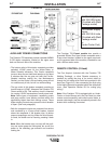
WORK CABLE CONNECTION
A 15ʼ (2/0) weld cable with clamp is available (K2150-1), or
included with the Precision TIG Welding Package model.
Otherwise, it is user provided.
With power source off, connect a separate work cable
to the 1/2-13 threaded "WORK" stud of the welder, and
secure a tight connection with the flange nut provided.
The work cable should be routed through the cable
strain relief hole provided in the base directly below the
welding output terminal.
Note: If the Precision TIG is equipped with an Under-
Cooler or Under-Storage unit, the coiled work cable
and clamp, or excess work cable length, may be con-
veniently stored in the drawer while remaining con-
nected.
STICK ELECTRODE CABLE CONNECTION
If manual stick welding is desired, with power source
off, connect a stick electrode cable to the 1/2-13
threaded "STICK Electrode" stud of the welder, and
secure a tight connection with the flange nut provided.
The electrode cable should be routed through the
cable strain relief hole provided in the base directly
below the welding output terminal.
DISCONNECT STICK ELECTRODE WELDING
CABLE WHEN TIG WELDING.
EVEN THOUGH HI-FREQ IS NOT APPLIED TO THE
PRECISION TIG STICK TERMINAL, IT WILL BE
ELECTRICALLY "HOT" TO WORK WHEN TIG
WELDING.
------------------------------------------------------------------------
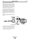
1. Connect the terminal marked (below the recon-
nect panel) to an earth ground.
2. Connect the input leads to terminals marked L1 (U)
and L2 (V) on the reconnect panel. Use a single
phase line or one phase of a two or three phase line.
3. On multiple input voltage welders, be sure the
reconnect panel is connected for the voltage being
supplied to the welder.
Failure to follow these instructions can cause
immediate failure of components within the welder.
------------------------------------------------------------------------
Welders are shipped connected for the highest input
voltage as listed on the rating plate. To change this
connection, designations on the reconnect panel LOW,
MID, and HIGH correspond to the name plated input
voltages of a triple voltage welder. Dual voltage
welders use only LOW and HIGH.
EXAMPLE: On a 208/230/460 volt welder, LOW is
208V, MID is 230V, and HIGH is 460V.
Note: Export model has a voltage range for LOW and
MID connections: LOW is 220-230V, MID is
380-400V and High is 415V.
Reconnect the jumper strap to the terminal stud corre-
sponding to the input voltage level used. Make sure all
connections are tight.
OUTPUT CABLES, CONNECTIONS AND
LIMITATIONS
• To avoid being startled by a high frequency
shock, keep the TIG torch and cables in good
condition
• Turn the power switch of the power source OFF
before installing adapters on cable or when con-
necting or disconnecting adapter plugs to power
source.
-----------------------------------------------------------------------
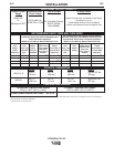
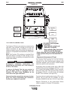
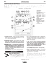
Refer to Figure A.2 for the location of the WORK and
STICK terminals, as well as the TIG Torch connection
panel.
WARNING
WARNING
CAUTION