


B-6
OPERATION
B-6
8. DIGITAL METER AND DISPLAY SWITCH– A (3-
digit) LED meter is used to monitor the preset and
actual welding procedure based on the Display
(momentary) switch position:
• Before welding with Display switch in center (normal)
position, the digital meter displays the preset welding
amps set by Maximum Output control knob (See Item
6). If in Stick mode using REMOTE (See Item 5.), the
digital meter displays the preset welding amps set by
the Remote control. (See Item 11)
• While welding with Display switch in center (normal)
position, the digital meter displays the actual welding
amps with one amp resolution (XXX) and accuracy
within 4%+/-2A of reading.
• Any time in TIG mode and while pressing the Display
switch to left, the digital meter displays the amps pre-
set by the Minimum Output control knob (See Item 7).
• Any time in Stick mode and while pressing the Display
switch to left, the digital meter displays the minimum
amps rating of the machine (See Item 7).
• Any time, in either mode, while pressing the Display
switch right to Volts position, the digital meter displays
actual output volts. Volts is displayed with 0.1 volt res-
olution (XX.X) and accuracy within 3%+/-1V of read-
ing.
• While pressing the (Menu) button when not welding
(see Menu Button and Display Button in previous
section), for Meter and Display switch functions.
9. POSTFLOW TIME – This knob is used to set the TIG
mode shielding gas postflow time over the range of
about 2 to 60 seconds after the arc is shut off. The
postflow on time status is indicated by the Green
panel light.
• Postflow Time is x2 extendable, if needed, by inter-
nal control box selection.
(
See Internal Set Up Controls)
• Gas preflow time for TIG mode is factory set at 0.5
second, but shorter times are selectable with the
Menu Button and Display Button.
10. THERMAL SHUTDOWN LIGHT – This yellow LED
panel light turns on if the machine output is shut-
down because internal overheating has occurred,
and turns off when the thermostat resets.
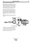
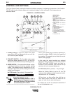
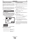
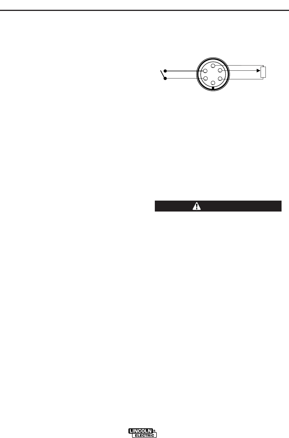
11. REMOTE RECEPTACLE – A 6-socket receptacle is
provided for the connection of an Amptrol, or other,
remote control: (See Figure B.2)
• When the Current Control Switch, (See Item 5), is in
the REMOTE position the Amptrol, or other remote
(10K pot), connected to the Remote receptacle con-
trols the TIG or Stick mode output within the range
preset by the Maximum and Minimum Output con-
trols. (See Item 6 and Item 7, also 8 for meter dis-
play)
• When the Current Control Switch is in either LOCAL
or REMOTE positions the arc start switch functions
when connected to the Remote receptacle.
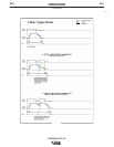
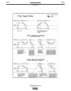
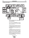
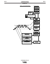
ADVANCED PANEL CONTROLS
The following controls are included only if the Precision
TIG 275 has the Advanced Control Panel (K2621-1)
option installed: (Refer to Section B-10 Tig Weld Cycle
Chart for graphic illustration of these TIG welding func-
tions.)
12. TRIGGER SWITCH – This 2-position switch
selects how the arc start switch ( connected to the
above Remote receptacle) functions; in 2-Step or 4-
Step mode:
• DO NOT USE 4-STEP IF USING AN AMPTROL
REMOTE.
• Neither the arc start switch nor the output con-
trol in the amptrol will function normally to shut
off or control the out put. ONLY USE 2-STEP.
------------------------------------------------------------------------
• In 2-Step position the arc start switch functions the
same as without the Advanced Panel:
1. Closing switch starts preflow, then a fixed
(0.5 sec.) ramp time from Minimum (Start)
setting level (See Item 7) to Weld setting.
2. Opening switch initiates Downslope ramp
time setting (See Item 17), from Weld set-
ting to Crater-fill level (See Item 7), which
then stops the arc and initiates Postflow
time (See Item 9).
Note: See Section B-7 for 2-Step operation during
Downslope with Restart feature selected to be dis-
abled, instead of enabled (as shipped).
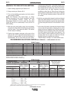
PRECISION TIG 275
A
B
C
D
E
F
Max
10K ohm
Min
REMOTE RECEPTACLE*
(Front View)
REMOTE OUTPUT
CONTROL
ARC START
SWITCH
*For 18-12P Plug
(LECO S12020-27)
CAUTION
FIGURE B.2