


B-7
OPERATION
B-7
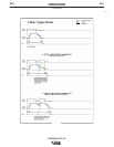
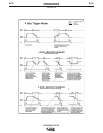
• In 4-Step position allows welding without continuously
holding the start switch trigger. The arc start switch func-
tions in the following manner:
1. Closing switch starts preflow, then arc starts at
Minimum (Start) setting level (See Item 7). If the
trigger is maintained closed after preflow time the
output remains at the Start level until it is
released.
2. Opening switch initiates fixed (0.5 sec.) ramp
time from Start setting level to Weld setting.
3. Reclosing switch initiates Downslope ramp time
setting (See item 17) from Weld setting down to
the Crater-fill level (See Item 7) of the machine.
4. Reopening switch after Downslope time holds
Crater-fill level until switch opens, then stops the
arc and initiates the Postflow Time (See Item 9).
Or, reopening switch during Downslope time
immediately stops the arc and initiates the
Postflow.
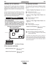
Note: (See Internal Set Up Controls) for 4-Step operation
during Downslope with Restart feature selected to be
enabled, instead of disabled (as shipped).
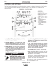
13. PULSE/SPOT MODE SWITCH – Turns on the Pulse
Mode as indicated by the Green panel light turning on.
• PULSE ON provides a Peak current level set by
REMOTE and/or LOCAL control of the output current (See
Item5), for a time determined by the Pulse Frequency
Control setting (See Item 14) and the % ON Time (See
Item 15). The balance of the cycle time is at the
Background Current level (See Item 16). The Green panel
light blinks at the pulse frequency and time setting rate.
• Pulsing begins after upslope when the output current rises
above the Background Current level and ends when the
output current drops below this level.
• SPOT ON mode provides the peak current level set by the
Maximum Output Control for a time determined by the
SPOT TIME control (see below). The red panel light is on
for Spot mode.
14. PULSE FREQUENCY CONTROL – This knob is used to
set the Pulse Frequency over the peak pulse range of
about 0.1 pps to 20 pps. (One pulse cycle time = 1/pps =
10 to .05 sec. range.)
15. PULSE % ON TIME/SPOT TIME CONTROL – This knob
sets the time for Pulse or Spot modes:
• % ON TIME sets duration of the peak current as a per-
centage (5% to 95% on white scale) of one pulse cycle.
The balance of the cycle time will be at the Background
Current setting. (See Item 16)
• SPOT TIME sets the duration of the Spot pulse (0.5 to 5.0
seconds on red scale).
16. PULSE BACKGROUND CURRENT CONTROL – This
knob controls the level of the Background Current as a
percentage (MIN.-100%) of the Peak (REMOTE and/or
LOCAL) output level (See Item 6) down to the Minimum
Output setting (See Item 7).
17. DOWNSLOPE TIME– This knob is used to set the time,
over the range of zero to about 10 seconds, to ramp
down from weld setting to Crater-fill level (See Item 7).
• If the arc goes out after the Downslope time is initiated,
the Downslope time is interrupted and the Postflow time is
initiated. This prevents Hi-Freq re-initiation during ramp
down crater fill
• When using an Amptrol remote control, where the downs-
lope is controlled by the operator down to the crater-fill
level, the Downslope time should be set to zero so as not
to have the Downslope time delay when the arc start
switch is opened.
PRECISION TIG 275