


B-8
OPERATION
B-8
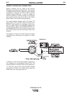
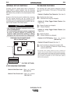
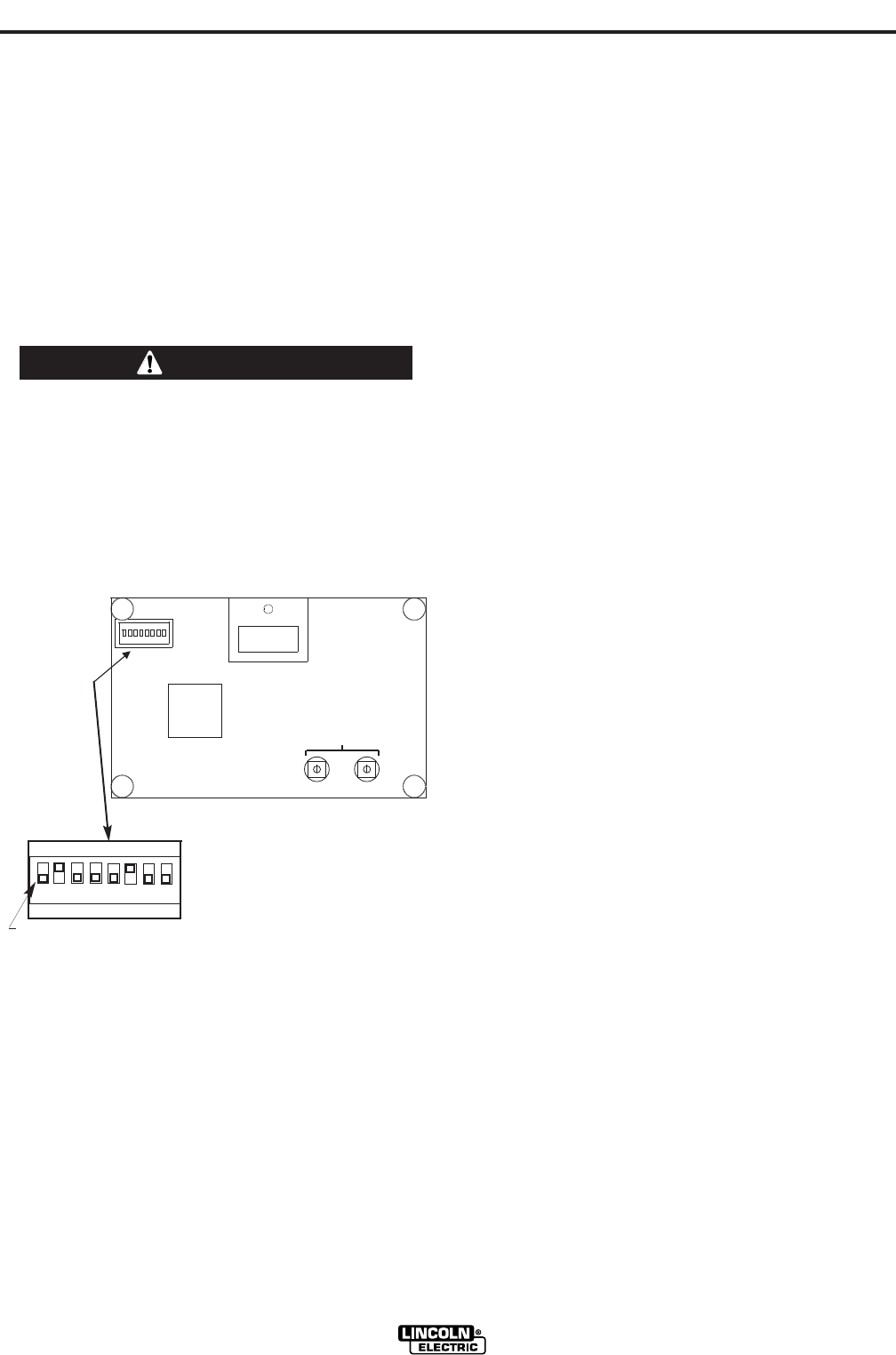
INTERNAL SET UP CONTROLS
Precision TIG 275 models which have an Advanced
Panel (K2621-1) option installed* have the following
additional control features which are set up using the
DIP Switch (S1) provided on the internal panel of this
option.
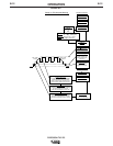
Access to this internal panel is obtained by removing
the two screws securing the top corners of the
Precision TIG front control panel and swinging the con-
trol panel down to reveal the panel mounted on the sur-
face of the Precision TIG Control board:
• THE CONTROL BOARDS CONTAIN STATIC SEN-
SITIVE COMPONENTS
• To avoid possible damage to these components
be sure to ground yourself by touching the
machineʼs sheet metal while handling or making
settings on the internal control box components.
------------------------------------------------------------------------
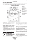
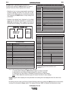
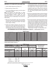
PRECISION TIG ADVANCED PANEL
(M21115 Internal Panel)
DIP SWITCH POSITIONS (FACTORY SETTINGS)
STICK WELDING FEATURES
• Switch #6 Hot Start Level – Does not function
(See
Item 7a)
• Switch #7 Arc Force Level – Does not function
(See
Item 7a)
TIG WELDING FEATURES
The following DIP switch feature selections function
only when the Precision TIG is set to TIG mode (See
Item 3):
• Switch #1 Postflow Time Extension* (See Item 9)
ON – Doubles the time range.
OFF – Standard time range (as shipped).
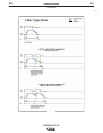
• Switch #2 2-Step Trigger Restart Feature (See
Figure B.3)
ON – Restart Enabled (as shipped).
OFF – Restart Disabled.
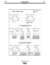
• Switch #3 4-Step Trigger Restart Feature (See
Figure B.4)
ON – Restart Enabled.
OFF – Restart Disabled (as shipped)
• Switch #4 Lift TIG Starting - Does not function
(See
Item 7a)
• Switch #5 Crater-Fill Level (See Item 7)
ON - Level is minimum rating of the machine (2A)
OFF – Level (as shipped) is Minimum Output setting
(same as Start level).
*
The Postflow Time doubling feature can also be selected on
Precision TIG 275 models without the Advanced Panel by access-
ing the Control board in the control box per above instructions,
then disconnecting the jumper terminals attached to the jumper
plug connected to receptacle J3 of the Control board. (Refer to
Machine Wiring Diagram.)
PRECISION TIG 275
CAUTION
HOT START
ARC FORCE
^ ON
1 2 3 4 5 6 7
DIP SWITCH (S1)
S F
ON
OFF
1234567
(DOES NOT FUNCTION)