


B-3
OPERATION
B-3
1. POWER SWITCH - Input line switch turns input
power ON or OFF, as indicated by the on or off sta-
tus of the front panel displays.
2. POLARITY SWITCH – The 3-position rotary power
switch has detente positions for DC-, AC and DC+
selections for the Electrode output welding polarity.
3. MODE SWITCH – The mode switch allows vertical-
ly positioned selection of the two machine welding
modes. The selected mode is indicated by a lit col-
ored panel light which permits viewing the machine
setting from a distance:
3.a STICK mode (Top position) –Red panel light
ELECTRIC SHOCK can kill.
• When the Power Source is ON in
STICK mode the Electrode circuits of
both the Stick and TIG torch cables
are electrically HOT to Work.
------------------------------------------------------------------------
• The CC Stick mode may be used for general pur-
pose stick welding (SMAW ) within the capacity of
the machine. The capacity is too limited for arc air
carbon (AAC) gouging.
• In this mode; the output terminals are activated
electrically HOT, gas flow is not activated and HOT
START and ARC FORCE levels are fixed, or
Advanced Panel selectable (See Internal Set Up
controls), with no front panel adjustment.
3.b TIG mode (Bottom position) – No panel light.
• When the Polarity Switch is set to AC, the TIG
mode provides continuous high frequency to stabi-
lize the arc for AC TIG welding.
Hi-Freq. turns on after preflow time with the arc
start switch closure, and turns off when the arc
goes out* after the arc start switch opens.
* Arc voltage and current are sensed to determine if
the arc is established or out.
PRECISION TIG 275
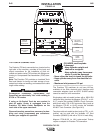
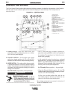
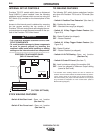
CONTROLS AND SETTINGS
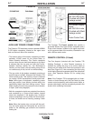
The Front Control Panel contains the knobs and switches necessary for adjusting the operation of the Precision
TIG 275, with function indicator lights and an electronic display for volts and amps. The components are
described below:
FIGURE B.1 - CONTROL PANEL
WARNING
1. POWER SWITCH
2. POLARITY SWITCH
3. MODE SWITCH
4. AC BALANCE CONTROL
5. LOCAL/REMOTE
CURRENT CONTROL
SWITCH
6. MAXIMUM OUTPUT CONTROL
7. MINIMUM OUTPUT CONTROL AND
DISPLAY SWITCH
7a. MENU BUTTON AND DISPLAY
SWITCH
8.
DIGITAL METER AND DISPLAY
SWITCH
9. POSTFLOW TIME
10. THERMAL SHUTDOWN LIGHT
11. REMOTE RECEPTACLE
12. TRIGGER SWITCH
13. PULSE / SPOT MODE SWITCH
14. PULSE FREQUENCY CONTROL
15. PULSE % ON TIME CONTROL
16. PULSE BACKGROUND CURRENT
CONTROL
17. DOWNSLOPE TIME
11
10
9
17
16
15
14
13
12
1
2
3
7
7a
8
9
5
6
4