


INPUT and GROUNDING CONNECTIONS
Be sure the voltage, phase, and frequency of the input
power is as specified on the rating plate, located on the
rear of the machine.
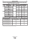
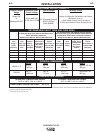
Fuse the input circuit with the recommended super lag
fuses or delay type1 circuit breakers. Choose an input
and grounding wire size according to local or national
codes or use Section A-2. Using fuses or circuit break-
ers smaller than recommended may result in "nui-
sance" tripping from welder inrush currents even if not
welding at high currents.
Unbalanced AC TIG welding draws higher input cur-
rents than those for Stick, DC TIG, or Balanced AC TIG
welding. The welder is designed for these higher input
currents. However, where unbalanced AC TIG welding
above 185 amps is planned, the higher input currents
require larger input wire sizes and fuses per Section A-2:
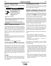
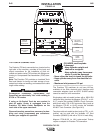
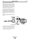
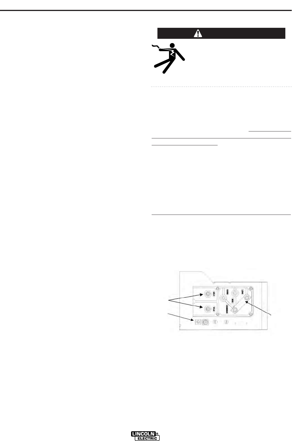
Remove the reconnect panel cover located near the
back of the left case side to reveal the reconnect panel.
Welder supply line entry provision is in the case rear
panel. Entry is through a 1.75 inch (44 mm) diameter
hole in the case back. Appropriate supply line strain
relief clamp is provided by installer. (See Figure A.1)
All connections should be made in accordance
with all local codes and national electrical codes.
Installation by a qualified electrician is recom-
mended.
A-4
INSTALLATION
PRECISION TIG 275
A-4
3. Be sure the torch and work cable rubber coverings
are free of cuts and cracks that allow high frequen-
cy leakage. Cables with high natural rubber content,
such as Lincoln Stable-Arc®, better resist high fre-
quency leakage than neoprene and other synthetic
rubber insulated cables.
4. Keep the torch in good repair and all connections
tight to reduce high frequency leakage.
5. The work terminal must be connected to a ground
within ten feet of the welder, using one of the fol-
lowing methods:
• A metal underground water pipe in direct contact
with the earth for ten feet or more.
• A 3/4" (19 mm) galvanized pipe or a 5/8" (16 mm)
solid galvanized iron, steel or copper rod driven at
least eight feet into the ground.
The ground should be securely made and the ground-
ing cable should be as short as possible using cable of
the same size as the work cable, or larger. Grounding
to the building frame electrical conduit or a long pipe
system can result in re-radiation, effectively making
these members radiating antennas. (This is not rec-
ommended).
6. Keep all access panels and covers securely in
place.
7. All electrical conductors within 50 feet (15.2 m) of
the welder should be enclosed in grounded rigid
metallic conduit or equivalent shielding. Flexible
helically-wrapped metallic conduit is generally not
suitable.
8. When the welder is enclosed in a metal building,
several good earth driven electrical grounds (as in 5
above) around the periphery of the building are rec-
ommended.
Failure to observe these recommended installation
procedures can cause radio or TV interference prob-
lems and result in unsatisfactory welding performance
resulting from lost high frequency power.
WARNING
ELECTRIC SHOCK can kill.
• Turn the input power OFF at the
disconnect switch or fuse box
before working on this
equipment.
FIGURE A.1
CONNECT INPUT
POWER LEADS
CONNECT INPUT
VOLTAGE LEVEL
CONNECT INPUT
GROUND LEAD