


B-13
OPERATION
B-13
PRECISION TIG 275
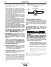
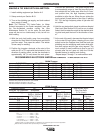
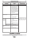
RECOMMENDED ELECTRODE AMPERAGE RANGES - PRECISION TIG 275
SMAW Process
ELECTRODE POLARITY 3/32" 1/8" 5/32"
Fleetweld 5P, Fleetweld 5P+ DC+ 40 - 70 75 - 130 90 - 175
Fleetweld 180 DC+ 40 - 80 55 - 110 105 - 135
Fleetweld 37 DC+ 70 - 95 100 - 135 145 - 180
Fleetweld 47 DC- 75 - 95 100 - 145 135 - 200
Jet-LH MR DC+ 85 - 110 110 - 160 130 - 220
Blue Max Stainless DC+ 40 - 80 75 - 110 95 - 110
Red Baron Stainless DC+ 40 - 70 60 - 100 90 - 140
Mild steel procedures are based on recommended procedures listed in C2.10 8/94 and the maximum rating of the PRECISION TIG 275
Excaliber 7018 procedures are based on Jet-LH 78 MR
Blue Max procedures are based on C6.1 6/95
Red Baron Procedure are based on ES-503 10/93
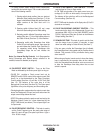
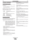
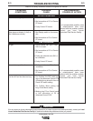
GTAW Process
Electrode Polarity DC- AC* Approximate Argon
Electrode Tip Preparation Sharpened Balled Gas Flow Rate
Electrode Type
EWZr C.F.H. (l/min.)
EWTh-1, EWCe-2 EWTh-1, EWTh-2
EWTh-2, EWLa-1 EWP EWCe-2, EWLa-1 Stainless
Electrode Size (in.) EWG EWG Aluminum Steel
.010 Up to 15 A. Up to 15 A. Up to 15 A. 3-8 (2-4) 3-8 (2-4)
.020 Up to 15 A. 10 to 15 A. 5 to 20 A. 5-10 (3-5) 5-10 (3-5)
.040 Up to 80 A. 20 to 30 A. 20 to 60 A. 5-10 (3-5) 5-10 (3-5)
1/16 Up to 150 A. 30 to 80 A. 60 to 120 A. 5-10 (3-5) 9-13 (4-6)
3/32 Up to MAX. A. 60 to 130 A. 100 to 180 A. 13-17 (6-8) 11-15 (5-7)
1/8 X 100 to 180 A. 160 to 250 A. 15-23 (7-11) 11-15 (5-7)
Tungsten electrodes are classified as follows by the American Welding Society (AWS):
Pure.........................................EWP...........green
+1% Thoria..............................EWTh-1......yellow
+2% Thoria..............................EWTh-2......red
+2% Ceria................................EWCe-2 .....orange
+1.5% Lanthana......................EWLa-1......black
+0.15 to 0.40% Zirconia..........EWZr..........brown
Ceriated Tungsten is now widely accepted as a substitute for 2% Thoriated Tungsten in AC and DC applications.
Balanced Wave, Unbalanced Wave requires derating of the electrode.
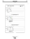
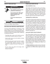
MAKING A TIG WELD WITH AN AMPTROL
1. Install welding equipment per Section A-5.
2. Setup controls per Section B-10.
3. Turn on the shielding gas supply, and torch coolant
input supply (if used).
Note: The Precision TIG Under-Cooler (or Water
Solenoid connected to the Cooler receptacle) runs with
the Fan-As-Needed machine cooling fan (See
Maintenance Section D), so the cooler fan and water
pump will also not run continuously in idle, but will run
while welding.
4. With the torch held safely away from everything,
close the Arc Start Switch of the Amptrol and set the
gas flow meter. Then open the switch. The welder
is now ready for welding.
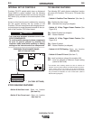
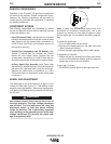
5. Position the tungsten electrode at the start of the
weld at a 65° to 75° angle with the horizontal, in the
direction of pushing travel, so that the electrode is
approximately 1/8" (4 mm) above the work piece.
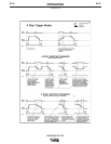
Close the arc start switch. This opens the gas valve
to automatically purge air from the hose and torch,
then shields the arc strike area. After the 0.5 sec-
ond preflow time, the high frequency becomes
available to strike the arc. When the arc strikes the
torch coolant (if used) starts to flow. Also, if welding
DC- TIG, the high frequency shuts off just after the
arc strikes.
6. Hold the arc start switch closed at minimum Amptrol
Start level (See Section B-10) until an arc is estab-
lished, then increase the output to the desired weld-
ing level and push the torch in the direction of trav-
el.
7. At the end of the weld, decrease the Amptrol output
to the crater-fill level before releasing the arc start
switch to start the Postflow time. Hold the torch gas
shielding over the solidifying weld crater while post-
flow time expires and the gas valve reopens. The
torch coolant (if used) continues to flow for up to 8
minutes after the arc goes out (with the Fan-As-
Needed feature) to assure torch cooling.
• Repeat steps 5 through 7 to make another weld.
*