


D-2
MAINTENANCE
D-2
SERVICE PROCEDURES
Operation of the Precision TIG should be trouble-free
for the life of the machine. Should a malfunction occur,
however, the following procedures will be useful to
trained service personnel with experience in repairing
arc welding equipment:
COMPONENT ACCESS
The following components are accessible for routine
set up and periodic service without requiring removal
of the case sides or roof:
• Input Reconnect Panel (refer Section A) is located
behind a removable panel on the rear of the left case
side. Remove the two screws (with a screwdriver or
a 3/8"/ 9.5mm hex driver) on the bottom corners of
this panel to remove it.
• Control Box components and PC Boards (refer
Section B Internal Set Up Controls) are located
behind the front control panel. Remove the two
screws (with a screwdriver or a 3/8"/ 9.5mm hex dri-
ver) on the top corners of this panel to swing it down.
• Hi-Freq. Spark Gap assembly (refer Spark Gap
Adjustment) is located behind a removable panel on
the rear of the right case side, under the torch box.
Remove the screw (with a screwdriver or a 3/8"/
9.5mm hex driver) on the bottom center of this panel
to remove it.
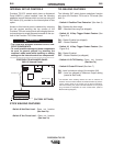
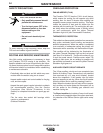
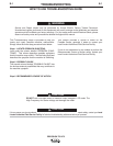
SPARK GAP ADJUSTMENT
The spark gap is set at the factory to a gap of 0.015
inches (0.4 mm) See Figure C.1. This setting is ade-
quate for most applications. Where less high frequen-
cy is desired, the setting can be reduced to 0.008 inch-
es (0.2 mm).
Use extreme caution when working with circuit of
the high frequency. The high voltages developed
can be lethal. Turn the input power off using the
disconnect switch or fuse box before working
inside the machine. This is particularly important
when working on the secondary circuit of the high
voltage transformer (T3) because the output volt-
age is dangerously high.
------------------------------------------------------------------------
Note: In highly dirty environments where there is an
abundance of conductive contaminants, use a low
pressure air stream or a firm piece of paper to clean
out the spark gap. Do not disturb the factory gap set-
ting.
To check the spark gap:
1. Turn the input power off per above.
2. Remove the access panel on the right case side
(See Component Access).
3. Check the spark gap spacing with a feeler gauge.
If adjustment is required:
1. Adjust the gap by loosening the Allen head screw
on one of the aluminum blocks, reset the gap and
tighten the screw in the new position.
If spark gap is correct:
1. Reinstall the access panel on the right case side.
PRECISION TIG 275
.015 Spark Gap
FIGURE C.1 SPARK GAP
WARNING