


A-5
INSTALLATION
COMMANDER 400
A-5
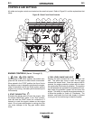
WELDING OUTPUT CABLES
With the engine off, route the electrode and work
cables thru the strain relief bracket provided on either
side of the base and connect to the terminals provided.
These connections should be checked periodically and
tightened if necessary.
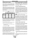
Listed in Table A.1 are copper cable sizes recom-
mended for the rated current and duty cycle. Lengths
stipulated are the distance from the welder to work and
back to the welder again. Cable sizes are increased for
greater lengths primarily for the purpose of minimizing
cable voltage drop.
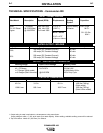
Table A.1 Combined Length of Electrode and Work
Cables.
MACHINE GROUNDING
Because this portable engine driven welder creates its
own power, it is not necessary to connect its frame to
an earth ground, unless the machine is connected to
premises wiring (home, shop, etc.).
To prevent dangerous electric shock, other equipment
powered by this engine driven welder must:
a) be grounded to the frame of the welder using a
grounded type plug,
or
b) be double insulated.
When this welder is mounted on a truck or trailer, its
frame must be securely connected to the metal frame
of the vehicle. When this engine driven welder is con-
nected to premises wiring such as that in a home or
shop, its frame must be connected to the system earth
ground. See further connection instructions in the sec-
tion entitled “Standby Power Connections” as well as
the article on grounding in the latest U.S. National
Electrical Code and the local code.
In general, if the machine is to be grounded, it should
be connected with a #8 or larger copper wire to a solid
earth ground such as a metal water pipe going into the
ground for at least ten feet and having no insulated
joints, or to the metal framework of a building which
has been effectively grounded. The U.S. National
Electrical Code lists a number of alternate means of
grounding electrical equipment. A machine grounding
stud marked with the symbol is provided on the
front of the welder.
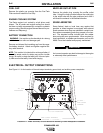
AUXILIARY POWER RECEPTACLES
The auxiliary power capacity of the Commander 400 is
10,000 watts of 60 Hz, single phase power. The auxil-
iary power capacity rating in watts is equivalent to volt-
amperes at unity power factor. The maximum permis-
sible current of the 240 VAC output is 44 A. The 240
VAC output can be split to provide two separate 120
VAC outputs with a maximum permissible current of 44
A per output to two separate 120 VAC branch circuits.
The output voltage is within ± 10% at all loads up to
rated capacity.
NO
TE: The 120/240V receptacle has two 120V outlets
of different phases and cannot be paralleled.
The Commander has two 15 Amp-120VAC (5-15R)
duplex receptacles with GFCI protection and one 50
Amp-120/240 VAC (14-50R) receptacle. The 120/240
VAC receptacle can be split for single phase 120 VAC
operation. The auxiliary power receptacles should only
be used with three wire grounded type plugs or
approved double insulated tools with two wire plugs.
The current rating of any plug used with the system
must be at least equal to the current capacity of the
associated receptacle.
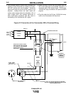
STANDBY POWER CONNECTIONS
The Commander 400 is suitable for temporary, stand-
by or emergency power using the engine manufactur-
er’s recommended maintenance schedule.
The Commander 400 can be permanently installed as
a standby power unit for 240 volt-3 wire, 44 amp ser-
vice. Connections must be made by a licensed electri-
cian who can determine how the 120/240 VAC power
can be adapted to the particular installation and com-
ply with all applicable electrical codes. The following
information can be used as a guide by the electrician
for most applications. Refer to the connection diagram
shown in Figure A.2.
1. Install the double-pole, double-throw switch between
the power company meter and the premises discon-
nect.
Switch rating must be the same or greater than the
customer’s premises disconnect and service over cur-
rent protection.
Up to 150
FT.
1 AWG
3/0 AWG
150-200 FT.
1 AWG
3/0 AWG
200-250 FT.
1/0 AWG
4/0 AWG
AMPS
@100%
Duty Cycle
250
400
TOTAL COMBINED LENGTH OF ELEC-
TRODE AND WORK CABLES