


B-5
OPERATION
B-5
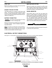
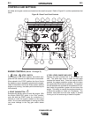
WELDER CONTROLS (Items 9 through 14 )
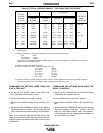
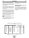
9. OUTPUT RANGE SWITCH & OUTPUT
CONTROL
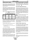
These two controls allow you to select between various
welding output slopes and adjust the desired welding
output. Refer to Table B.1 for a description of how
these two controls work.
Table B.1 Output Range Switch and Output Control
Functions
1
If the OUTPUT RANGE switch is positioned between settings the
previous setting is maintained until the switch is properly positioned
on a setting.
2
OUTPUT CONTROL also controls O.C.V.while in the 6 sloped out-
put ranges.
10. DIGITAL OUTPUT METER
The digital output meter is located in the center of the
control panel between the two large control knobs. The
meter allows the output current level to be set prior to
welding. During the welding process the meter dis-
plays the actual output current.
11. WELDING TERMINALS SWITCH
The toggle switch on the control panel labeled
“Welding Terminals Always On” and “Welding
Terminals Remotely Controlled”: is used to control the
operation of the “solid state contactor” which allows for
the selection of “Hot” or “Cold” welding terminals.
With the switch in the “Welding Terminals Always On”
position the contactor is closed and the welding termi-
nals are always “Hot”.
With the switch in the “Welding Terminals Remotely
Controlled” position the contactor operation is con-
trolled by an Amptrol, Arc Start Switch or some other
type of triggering device through the use of a control
cable connected to the 6-pin MS connector.
When the triggering device is pressed the contactor is
closed and the welding terminals are “Hot”.
When the triggering device is released the contactor is
opened and the welding terminals are “Cold”.
12. LOCAL /REMOTE SWITCH
The toggle switch on the control panel labeled
“Local/Remote” gives the operator the option of con-
trolling the output at the welder control panel or at a
remote station.
For remote control the toggle switch is set in the
“Remote” position.
For control at the welder control panel, the toggle
switch is set in the “Local” position.
13. 6 - PIN CONNECTOR
The 6-pin connector located on the control panel
allows for connection of Remote Control accessories.
14. WELD OUTPUT TERMINALS + AND -
These 1/2 - 13 studs with flange nuts provide welding
connection points for the electrode and work cables.
For positive polarity welding the electrode cable con-
nects to the “+” terminal and the work cable connects
to this “-” terminal. For negative polarity welding the
work cable connects to the “+” terminal and the elec-
trode cable connects to this “-” terminal.
AUXILIARY POWER CONTROLS
(Items 15 - 19 )
15. 120/240VAC RECEPTACLE
This is a 120/240VAC (14-50R) receptacle that pro-
vides 240VAC or can be split for 120VAC single phase
auxiliary power. This receptacle has a 50 amp rating.
Refer to the AUXILIARY POWER RECEPTACLES sec-
tion in the installation chapter for further information
about this receptacle. Also refer to the AUXILIARY
POWER OPERATION section later in this chapter.
16. 50 AMP CIRCUIT BREAKERS
These circuit breaker provide separate overload cur-
rent protection for each 120V circuit at the 240V recep-
tacle.
COMMANDER 400
Sloped Output for
Pipe Welding.
(all models)
Constant Current
Output for
Fabrication and
General Purpose
Welding (This set-
ting also used for
TIG) (all models)
Constant Voltage
Output for Wire
Welding (Stick &
Wire model only)
6 Range
Settings
90, 120, 180,
230, 270, 400
(Max. current on
each setting)
1 Range setting
50-575 Amps
1 Range setting
12 to 40 Volts
Provides a fine
adjustment of
welding current
or voltage from
Min (1) to Max
(10) within each
range
Range
Switch
1
Control
2