


B-9
OPERATION
B-9
WIRE FEED (CONSTANT VOLTAGE) WELD-
ING
(Stick and Wire models only)
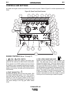
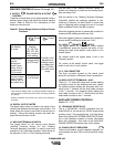
Connect a wire feeder to the Commander 400 and set the
welder controls according to the instructions in “Controls
and Settings” in this section of the manual.
The Stick and Wire model of the Commander 400 with its
CV tap, permits it to be used with a broad range of flux
cored wire (Innershield and Outershield) electrodes and
solid wires for MIG (GMAW).
For any electrodes, the procedures should be kept within
the rating of this machine. For additional electrode infor-
mation, see Lincoln publications N-675, GS-100 and GS-
210.
STICK AND WIRE MODEL CONNECTION TO
LN-25
The LN-25 with or without an external contactor may be
used with the Commander 400 Stick and Wire model. See
the appropriate connection diagram in “DIAGRAMS” sec-
tion. NOTE: The LN-25 (K431) Remote Control Module
and (K432) Remote Cable are not recommended for use
with the Commander 400 S&W.
a. Shut the welder off.
b. For electrode Positive, connect the electrode cable
from the LN-25 to the “+” terminal of the welder and
work cable to the “- WIRE” terminal of the welder.
For electrode Negative, connect the electrode cable
from the LN-25 to the “ WIRE” terminal of the welder
and work cable to the “+”terminal of the welder.
c. Attach the single lead from the front of the LN-25 to
work using the spring clip on the end of the lead.
This is a control lead to supply current to the wire
feeder motor; it does not carry welding current.
d. Set the range switch to “WIRE WELDING CV”
e. Set the “OUTPUT CONTROL” switch to “WELDING
TERMINALS ALWAYS ON”
f. Set the “VOLTS\AMPS” switch to “VOLTS”
g. Set the “IDLE” switch to the “AUTO” position. When
not welding , the Commander 400 S&W engine will
be at the low idle speed. CAUTION: ( if you are
using an LN-25 without an internal contactor, the
electrode will be energized when the Commander
400 Stick and Wire model is started.) If you are
using an LN-25 with an internal contactor, the elec-
trode is not energized until the gun trigger is closed.
In either of the LN-25 wire feeders, when the gun
trigger is closed, the current sensing circuit will
cause the Commander 400 Stick and Wire model
engine to go to the high idle speed, the wire will
begin to feed and the welding process started.
When welding is stopped, the engine will revert to
low idle speed after approximately 15 seconds
unless welding is resumed.
STICK AND WIRE MODEL CONNECTION TO
LN-7 or LN-8
a. Shut the welder off.
b. Connect the LN-7 or LN-8 per instructions on the
appropriate connection diagram in “DIAGRAMS”
section. Set the “LOCAL REMOTE” switch to
“REMOTE” for the LN-7 and LN-8 with a K857
remote voltage control cable attached; “LOCAL” for
LN-7 with no remote voltage control.
c. Set the “VOLTMETER” switch to either “+” or “-” as
required by the electrode being used.
d. Set the “RANGE” switch to the “WIRE WELDING
CV” position.
e. Set the “OUTPUT CONTROL” switch to the “OUT-
PUT REMOTELLY CONTROLLED” position.
f. Set the “IDLE” switch to the “HIGH” position.
When the gun trigger is closed, the electrode is energised
and the wire will begin to feed.
------------------------------------------------------------------------
STICK AND WIRE MODEL CONNECTION TO
LN-23P
a. Shut the welder off.
b.
Connect the LN-23P as per instructions on the
appropriate connection diagram in “DIAGRAMS”
section. NOTE: When connecting an LN-23P to the
Commander Stick & Wire, a K350-1 adapter kit must
be used. Set the “VOLTMETER” switch to either “+”
or “-” as required by the electrode being used.
d. Set the “RANGE” switch to “WIRE WELDING CV”
e. Set the “OUTPUT CONTROL” switch to “WELDING
TERMINALS ALWAYS ON” Set the “VOLTS/AMPS”
switch to “VOLTS”
g. Set the “LOCAL REMOTE” switch to the desired
setting depending upon where the power sources
output is being controlled from.
h. Set the “IDLE” switch to the “AUTO” position. When
not welding , the Commander 400 Stick and Wire
model engine will be at the low idle speed. If you are
using an LN-23P with the K350-1 adapter kit, the
electrode is not energized until the gun trigger is
closed. When the gun trigger is closed, the current
sensing circuit will cause the Commander 400 Stick
and Wire model engine to go to the high idle speed,
the wire will begin to feed and the welding process
can be started. When welding is stopped, the
engine will revert to low idle speed after approxi-
mately 15 seconds unless welding is resumed.
STICK AND WIRE MODEL CONNECTION TO
NA-3
For connection diagrams and instructions for connecting
an NA-3 Welding System to the Commander Stick & Wire,
refer to the NA-3 Welding System instruction manual.
COMMANDER 400
CAUTION