


A-1
INSTALLATION
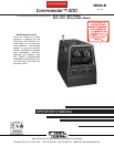
COMMANDER 400
A-1
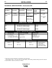
TECHNICAL SPECIFICATIONS - Commander 400
Make/Model Description Speed (RPM) Displacement Starting Capacities
System
Deutz 3 cylinder High Idle 1900 173 cu. in 12VDC battery Fuel: 25 gal.
F3L 912 Diesel 44.2 HP(33kw) Low Idle 1350 (2.827 L) & Starter 94.6 L
Engine @ 1800 RPM Full Load 1800
Bore x Stroke Oil: 8.5 Qts.
8.04 L
3.94” x 4.72”
(100mm x 120mm)
INPUT - DIESEL ENGINE
RATED OUTPUT - WELDER
HEIGHT
2
WIDTH DEPTH WEIGHT
42.0 in. 31.5 in. 63.1 in. 1650 lbs.(748 kg)
(Stick model)
1066.8 mm 800.1 mm 1602.7 mm 1683 lbs.(763 kg)
(Stick & Wire model)
OUTPUT - WELDER AND GENERATOR
Duty Cycle Welding Output Volts at Rated Amps
100%
400 amps (DC Constant Current) 40 volts
400 amps (DC Constant Voltage) 40 volts
60%
500 amps (DC Constant Current) 40 volts
500 amps (DC Constant Voltage) 40 volts
Welding Range Open Circuit Voltage Auxiliary Power
1
40 - 575 Amps 64-74 OCV 120/240 VAC
in 7 Ranges (Stick model) 10,000 Watts, 60 Hz.
or 8 Ranges
(Stick & Wire model)
@1915 RPM 100% Duty Cycle
PHYSICAL DIMENSIONS
1. Output rating in watts is equivalent to volt-amperes at unity power factor.
Output voltage is within +/- 10% at all loads up to rated capacity. When welding, available auxiliary power will be reduced.
2. Top of Enclosure. Add 6.64” (168.7mm) for exhaust.