


B-4
OPERATION
B-4
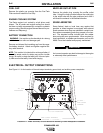
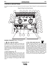
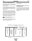
4. ENGINE TEMPERATURE GAUGE AND
LIGHT
The gauge displays the engine oil temperature. The
yellow temperature light remains off under normal
operating temperatures. If the light turns on, the
engine protection system will shut down the engine.
Check for restrictions at the engine cooling air inlets
and outlets (consult the engine Operator’s Manual).
Check for loose or disconnected leads at the tempera-
ture sender located on the engine. Check engine cool-
ing blower belt. Also, check to be sure that the welder
loads are within the rating of the welder. The light will
remain on when the engine has been shut down due to
an over- temperature condition.
5. OIL PRESSURE GAUGE AND LIGHT
The gauge displays the engine oil pressure when the
engine is running. The yellow oil pressure light
remains off with proper oil pressure. If the light turns
on, the engine protection system will stop the engine.
Check for proper oil level and add oil if necessary.
Check for loose or disconnected leads at the oil pres-
sure sender located on the engine. The light will go on
and stay on when the RUN-STOP switch is switched to
the “Run” position with engine not running.
6. ENGINE ALTERNATOR AMMETER
AND LIGHT
The yellow engine alternator light is off when battery
charging system is functioning normally. If light turns
on, the engine protection system will shut down the
engine. Check the engine cooling blower belt. Also,
the alternator or the voltage regulator may not be oper-
ating correctly. The light may also come on if the alter-
nator did not flash up due to not holding the start but-
ton in long enough (minimum of 2 seconds) or due to a
faulty flashing circuit. The light will remain on when the
engine has been shut down due to a fault in the alter-
nator, regulator, or the cooling blower belt.
7. IDLER SWITCH
Has two positions as follows:
A) In the “High” position , the engine runs at
the high idle speed controlled by the governor.
B) In the “Auto” / position, the idler oper-
ates as follows:
a. When switched from “High” to “Auto” or after
starting the engine, the engine will operate at full
speed for approximately 15 seconds and then go
to low idle speed.
b. When the electrode touches the work or power is
drawn for lights or tools (approximately 100 Watts
minimum) the engine accelerates and operates
at full speed.
c. When welding ceases or the AC power load is
turned off, a fixed time delay of approximately 15
seconds starts.
d. If the welding or AC power load is not restarted
before the end of the time delay, the idler reduces
the engine speed to low idle speed.
e. The engine will automatically return to high idle
speed when the welding load or A.C. power load
is reapplied.
Idler Operational exceptions
When the WELDING TERMINALS switch is in the
“Welding Terminals Remotely Controlled” position the
idler will operate as follows:
a. When the triggering device (Amptrol, Arc Start
Switch, etc.) is pressed the engine will accelerate
and operate at full speed provided a welding load is
applied within approximately 15 seconds.
• If the triggering device remains pressed but no weld-
ing load is applied within approximately 15 seconds
the engine will return to low idle speed.
• If the triggering device is released or welding ceases
the engine will return to low idle speed after approxi-
mately 15 seconds.
8. HOUR METER
The hour meter displays the total time that the engine
has been running. This meter is a useful indicator for
scheduling preventive maintenance.
COMMANDER 400