


P 12/20
Repair
[3] DISASSEMBLY/ASSEMBLY
[3]-5. Air Motor Section
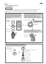
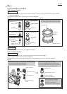
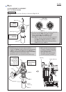
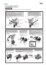
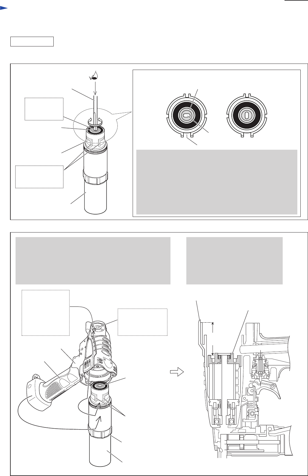
Fig. 22
Fig. 23
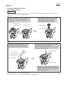
4) Assemble Air motor section to Housing as illustrated in Figs. 22, 23.
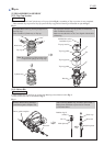
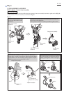
2. Hold Housing over Air motor section on 1R273.
In order to fit Rib B (located on Grip side inside Housing)
in Ribs A, while watching Hole A through Hole B of
Housing, turn Housing or Air motor section so that Hole A
is positioned vertical (or horizontal) to Grip.
Put Housing down over Air motor section until it stops.
1R273
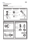
Driver bit
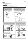
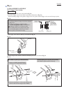
1. First, for easy assembling, make the following adjustment:
Insert Driver bit into Hole A of Carrier complete.
Then, by turning Driver bit, set Hole A vertical
(or horizontal) to Ribs A of Internal gear 44.
Note: Ribs A cannot be seen when assembling Air motor
section to Housing although alignment of Ribs A
with Rib B (See Fig.23) of Housing is required.
This adjustment will be able to know the position
of Ribs A from that of Hole A.
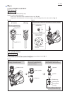
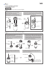
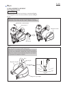
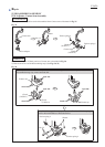
Upper drum cap
Housing
approx.
43.5mm
3. Make sure that Air motor section
is properly assembled to Housing
by measuring the depth indicated
in the illustration below.
The depth will be approximately
43.5mm if properly assembled.
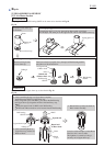
ASSEMBLING
Carrier complete
[Top view]
Hole A
Carrier complete
Ribs A
Hole A:
insertion hole
for Driver bit
Internal gear 44
Ribs A:
with larger
intervening width
Grip
1R273
Ribs A
Rib B:
located on
the inside surface
of Housing end,
positioned on
Grip side,
widest of the four
Upper
drum cap
Housing
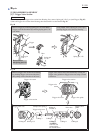
Hole A
Hole B:
Hole for Driver bit
on the end surface
of Housing