


P 16/20
Repair
[3] DISASSEMBLY/ASSEMBLY
[3]-7. Trigger Valve Section
Fig. 30
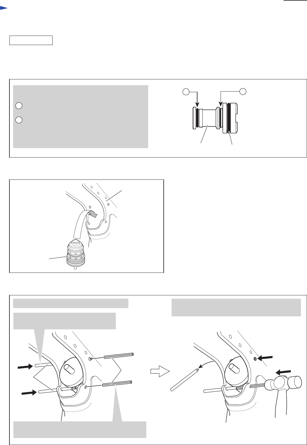
Fig. 32
Fig. 31
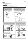
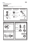
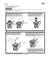
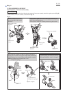
1) Mount O rings to Pilot valve as described in Fig. 30.
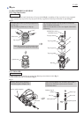
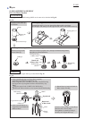
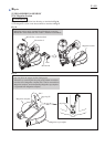
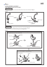
2) Assemble Trigger valve section. (Refer to the bottom illustration in Fig. 29.)
When assembling Trigger valve guide to Trigger valve case, push it toward Trigger valve case until it snaps in place.
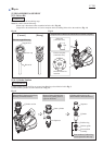
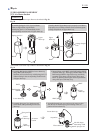
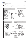
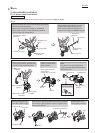
3) Set Trigger valve section in Housing as illustrated in Fig. 31.
4) Secure Trigger valve section to Housing with Spring pin 3-28 as described in Fig. 32
Two different kinds of O rings of size 8 are mounted
on Pilot valve:
A O Ring 8 (213984-5), of Nitrile rubber,
with one side painted white for identification
B O Ring 8 (213985-3), of Urethane rubber
Do not confuse these two O rings because they
are not interchangeable, and be sure to mount
them in position as illustrated on right.
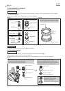
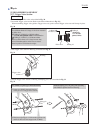
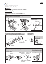
Use 1R268 as a guide jig as illustrated below. Strike the Spring pin 3-28 gently and repeatedly
until 1R268 is pushed out from Housing.
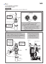
ASSEMBLING
O Ring 18
O Ring 8
(213984-5),
with one side
painted white
O Ring 8
(213985-3)
Pilot valve
B
A
Trigger valve
section
Housing
1R268
Spring pin
3-28
1. Insert two 1R268’s through Housing
in the groove of Trigger valve section.
2.Then insert Spring pin 3-28 from the opposite side,
and fit its hole over the stepped end of 1R268.