


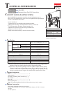
P 5/20
Repair
[3] DISASSEMBLY/ASSEMBLY
[3]-2. Top Cap Section
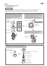
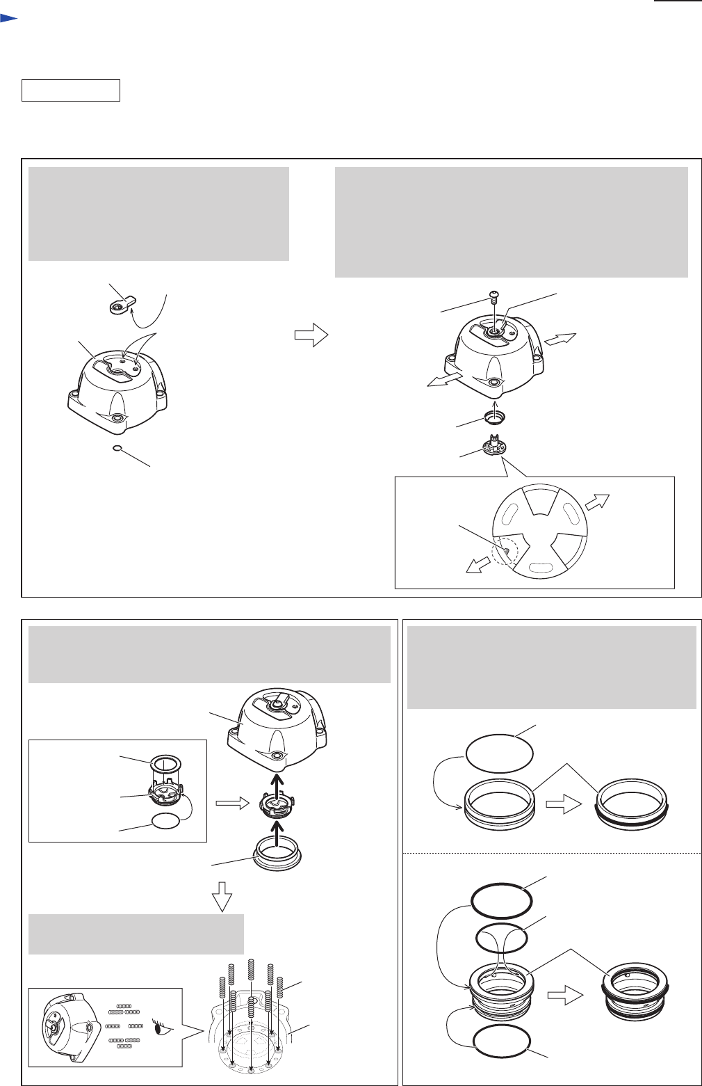
1) Assemble Top cap section as described in Figs. 5, 6.
2) Assemble O rings to Cylinder stay and Head valve as described in Fig. 7.
ASSEMBLING
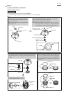
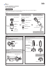
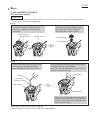
Fig. 5
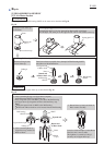
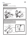
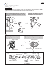
Fig. 6 Fig. 7
click-stop concave
portion
protrusion
Knob
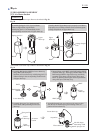
Set Knob on Top cap, with the protrusion on
its back fitting in either click-stop concave
portions on Top cap.
Then assemble O ring 6 to the insertion hole
for Change valve.
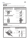
Assemble Conical compression spring 10-15 to Top cap
with the small end on Change valve side.
Then assemble Change valve to Top cap.
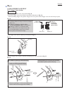
Note: When assembling Change valve to Top cap, place the
notch on the front side of Top cap as illustrated below
so that Change valve can engage with Knob easily.
Top cap
O Ring 6
Front side
Rear side
Change valve
Conical compression
spring 10-15
Knob
M4x8 Hex socket
button head bolt
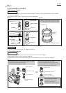
Top cap
Seal ring
O Ring 54
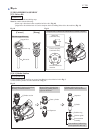
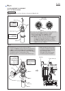
Before assembling Cylinder stay and Head valve
to Top cap, mount O rings to them as illustrated
below, then apply such an amount of IDOFLEX
grease that they are covered with a thick layer of
the grease.
After mounting O ring 22 and Flat washer 19 on Rear cushion,
assemble Rear cushion to Top cap, then assemble Seal ring to
Top cap.
Set Compression spring 4 (8 pcs)
in the big diameter holes of Top cap.
Cylinder stay
Head valve
O Ring 47
O Ring 40
O Ring 45
Front side
notch
Rear side
Flat washer 19
Rear cushion
O Ring 22
Top cap
Compression
spring 4