


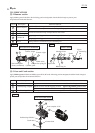

Piston
Connecting rod
P 11/ 20
Repair
[3] DISASSEMBLY/ASSEMBLY
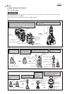
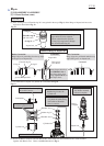
[3]-4. Bearing box section, Crank housing section
DISASSEMBLING
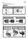
Fig. 23 Fig. 24
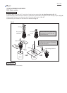
Filter case cover and Filter case (Re: Fig. 20)
can be disassembled.
O ring 72 and O ring 14 can be removed from
Bearing box complete and Grease cap
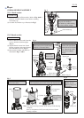
Filter case
Filter
Filter case cover
O ring 18
O ring 45
O ring 71
Grease cap
Bearing box complete
O ring 14
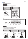
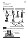
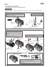
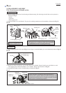
(6) In the step of Fig. 21 (after removing Bearing box complete), Piston can be disassembled from Crank housing
complete as illustrated in Fig. 25.
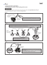
(7) Crank shaft section can be disassembled as illustrated in Fig. 26.
Align Piston, Connecting rod and Crank shaft
on their center line by turning Crank shaft, .
Piston can be removed from Crank housing
complete together with Connecting rod.
Piston
Connecting rod
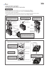
To stabilize Crank housing during
disassembly, put it onto 1R217.
And apply 1R246 to Crank shaft
and press down Crank shaft.
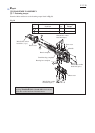
Apply 1R247 to Ball bearing
6203LLU from Bearing box
complete side, and press down
Ball bearing 6203LLU.
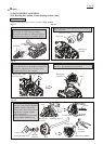
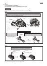
Helical gear 52 and Crank
shaft section are disassembled
as illustrated below.
Crank shaft
Crank Shaft
1R246
Crank housing
complete
Fig. 25
Fig. 26
1R247
Helical gear 52
Crank Shaft
Ball bearing
6304LLU
Ball bearing
6203LLB
Ball bearing 6203LLB
Oil seal 20
1R217
Crank housing complete