


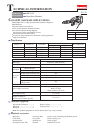
P 5/ 20
Repair
[3] DISASSEMBLY/ASSEMBLY
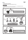
[3]-1. Chuck section
[3]-2. Barrel section
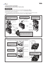
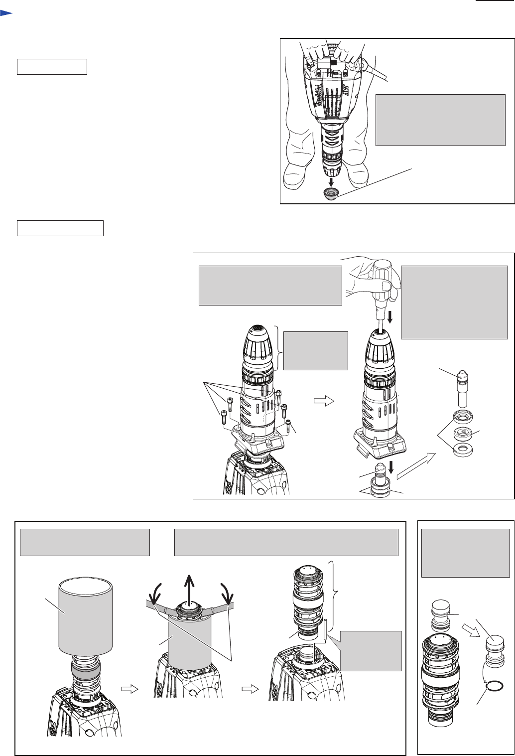
DISASSEMBLING
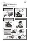
ASSEMBLING
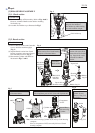
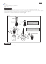
Fig. 5
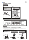
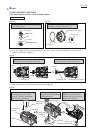
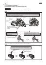
Fig. 6
(1) Do the reverse step of Disassembly. Refer to Figs. 4and 3.
However, assemble Handle section before mounting
Tool holder cap.
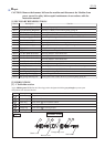
(2) Assemble Tool holder cap as illustrated in Fig.5.
Put Tool holder cap on ground,
and push Tool holder to
Tool holder cap while making
use of the machine weight.
Tool holder cap
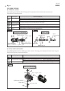
(1) Remove Handle section and Controller
cover to hold the machine upright.
(Fig. 2)
(2) Separate Barrel section from Crank
housing complete, and remove Impact
bolt from Barrel section. (Fig. 6)
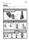
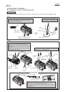
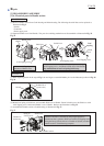
(3) Disassemble Cylinder and Striker as
illustrated in Figs. 7 and 8.
M8x30 Hex
socket head
bolt (4pcs.)
No need to
disassemble
Chuck section.
Push the removed Barrel
section with screwdriver
inserted from Tool holder
cap. Impact bolt can be
removed from Barrel
section.
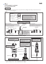
Separate Barrel, Barrel cover and
Chuck section from Crank housing
complete as illustrated below.
M6x30 H.S
head bolt
with GM
Impact bolt
Rubber ring 24
Impact bolt
Shoulder
sleeve
Rubber
ring 24
Shoulder sleeve
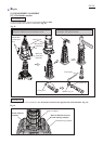
1R023
Note: Even after removing Cylinder 40, do not lay Crank housing
complete,
Pin 6 (a component of AVT) can easily fall out of Crank
housing complete.
1R023
Striker
Take out Striker from
Cylinder 40, and
Remove O ring 31.5
from Striker.
O ring 31.5
1R263
Cylinder 40
Pull off Pin 6
after removing
Cylinder.
Put 1R023 onto Crank housing
as illustrated below.
Remove Cylinder 40 and Pin 6, as illustrated below.
The component parts of AVT come with Cylinder 40.
Fig. 7
Fig. 8
Components
of AVT